It’s been a while since I’ve posted due to HSBNE’s lockdown due to COVID-19. However, a lot has been happening and I’ve put up a new blog post. There’s a copy of it below, but be sure to view it on my blog for best results.
I hope everyone is staying safe and healthy during the current COVID-19 global pandemic. It’s affected this project as I had to put in on pause during our mandated lockdowns. A lot has happened since my last post! Unfortunately my friend Matthew is too busy to work on the project so I’ve taken it over completely now.
I’ve decided on the ZEVA EVMS for the traction pack BMS. This is a hybrid BMS and EV control system. It has many great features, like: contactor control, motor controller precharge, integration with CAN bus chargers, detection of traction circuit isolation faults, battery state of charge, CAN bus API, etc. Overall this system was the best value in terms of price and features. It is even made right here in Australia. The CAN bus API also means it can be easily integrated into the touch screen dashboard further down the track.
It’s a pretty neat system, and is very modular / configurable. This will allow for future expansion and design changes relating to the traction pack. There are 4 main components of the system, of which are summarised and explained below.
Note: all images were sourced from the www.zeva.com.au website.
The EVMS (Electric Vehicle Management System) “master unit”
This is just called the EVMS, but it acts like the “master unit” or brains of the whole system. An example wiring diagram from their user manual has been included below. As you can see this EVMS serves two main purposes. Firstly, it acts as the BMS system. It monitors the battery state of charge (SOC), current in/out of the battery and individual cell voltages. Secondly, it acts as an EV controller. This means it takes care of things like the main and auxiliary contactors; monitoring insulation integrity of the traction system; start, stop and control of a connected charger via CAN, and a few other useful things.
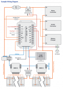
A diagram showing all of the components that make up a typical EV traction system controlled by an EVMS.
EVMS BMS-12
The EVMS BMS-12 module monitors up to 12 lithium battery cells in series. You can add multiple of these BMS modules in series and parallel. The ID selector on board allows you to select a unique ID. This means you can have up to 16 of these BMS units connected to the same EVMS master unit. They also have shunt resistors in them that are used for balancing the packs at up to 120mA. This is a pretty decent balancing rate. The current traction pack battery will probably be around 26s or 96v nominal which means I need 3 of these.
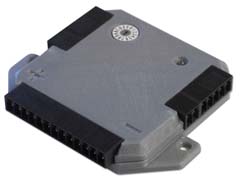
The EVMS BMS-12 module. You can see the 12S cell connector on the bottom with other connectors for the CAN bus.
EVMS CAN Current Sensor
ZEVA have two types of CAN based current sensors. The first is a hall effect type which goes around one of your traction pack wires. The other one is a shunt type that you wire in series with one of your traction pack wires. I chose the hall effect type as it will be a little bit easier/cleaner to install. The version I got will measure up to 300A of current. This should be suitable for the expected 220A peak current draw of the entire system. Try to source the smallest rated version you can get away with, as they will generally give you the most resolution/accuracy.
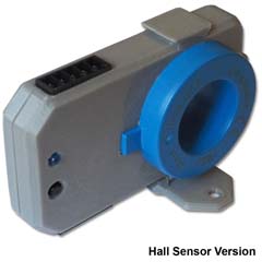
The EVMS CAN current sensor with the CAN bus connector on top and the blue ring you feed a traction pack wire through.
EVMS Monitor V3
The EVMS monitor is a small screen that connects to the EVMS CAN bus. It allows you to view pack voltage, current, power, state of charge, temperature and auxiliary voltage, among others. It also allows you to configure the EVMS system and a range of devices that are on the CAN bus. You can configure things such as system cell count, min/max voltage cutoff, etc. The EVMS monitor will be initially used while developing the motorcycle. However, later on it will most likely be replaced with the custom touch screen dashboard that I’m developing. I chose the panel mount version so I can integrate it into the bike more permanently if I end up deciding to do that.
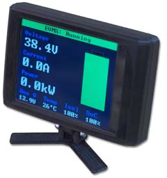
The EVMS monitor showing an example of the current system voltage and other information.
Powertrain Selection (QS Motor 8/16kW)
I’m happy that I’ve finally decided on a motor. After talking with the QS Motor sales team, I’ve decided on their 8,000/16,000 watt hub motor. I still haven’t quite decided on a controller yet, but I’m leaning towards a Sevcon one as they look very nice. This motor has a continuous rating of 8kW and a peak rating of 16kW. I think it also has very short burst rating of about 20kW, but I’m unsure. The ideal nominal battery voltage is 96v (109v fully charged). I expect to get really good performance out of this motor – in the order of a ~5 second 0-100km/hr time. This of course depends on the final traction pack, bike weight and motor controller. This should exceed the performance of my 310cc BMW G310r all while not making any noise – this makes me very happy :).
The higher powered version (12/24kW) was originally what I wanted. However, the total cost for the motor and controller goes up quite a bit, and I’d need to widen the rear dropout. The QS motor sales team were very helpful and convinced me to go down from the 12kW to the 8kW as it was better suited to my needs. They are trying to sell me an APT 96600 controller. The APT doesn’t have a CAN bus for configuration, throttle control or monitoring real time data like RPM. All of which I’d really like, but aren’t a hard requirement. I also can’t find almost anything about this controller online so I’m hesitant to use it and will likely go with a Sevcon one.
ELV Auxiliary Power System (12v)
Even EVs need a low voltage auxiliary power system. There are two main reasons for this. The first is it’s simply easier to run all of your headlights, dashboard, and other standard automotive equipment off of 12v. The second is a legal requirement under the VSB 14 NCOP (national code of practice) for electric vehicle conversions. The last line is important to observe when speccing out a suitable battery capacity to use. The relevant excerpt is included below for reference.
An independent auxiliary ELV (nominally 12V) must be used to guarantee the supply of power to safety equipment such as lights, brake boosters and windscreen wipers in the event of a shutdown of the main battery system in the vehicle. … The auxiliary supply must be capable of operating the hazard lights (four-way flashers) at normal duty cycle, for a minimum period of 20 continuous minutes.
Vehicle Standards Bulletin (VSB 14) – National Code of Practice for Light Vehicle Construction and Modification
I haven’t decided yet what battery I’m going to use for the ELV system, but I’m thinking of one of those small 12v LiFePO4 batteries with a built in BMS etc. These are about 1.5-2x more expensive than a 12v lead acid battery but are around half the weight, last significantly longer (5-10 years vs 1-3 years), and are a drop in replacement for lead acid batteries. This means I can use any standard 300W – 500W DC DC converter that charges a 12v lead acid battery like the elcon or sevcon units.
Conclusion
I’ve spent countless hours over the last few weeks researching different options so I am hopeful that I’ve made the right decision. All of the parts from ZEVA above have been ordered and should be with me in the next couple of weeks. I also ordered a Gigavac GV241BAX 400A DC contactor for the main traction pack (way higher rated than I need, but ZEVA had them in stock so it was easier), and a ZEVA 12v low voltage cut off for the ELV system. This will allow me to start running some experiments necessary for developing the main traction pack and ELV system. My credit card has already had enough of a work out for the time being, so I’ll be ordering the motor and controller in a few weeks when it’s had a chance to recover  .
.
You can also see this on my blog here .