I ripped apart a desktop laser printer (the one that had been rained on and had dirt all through it!) and got a tiny polygon mirror assembly that I managed to drive successfully (video link): https://goo.gl/photos/rCWJJtpNKZ2DT3cK8
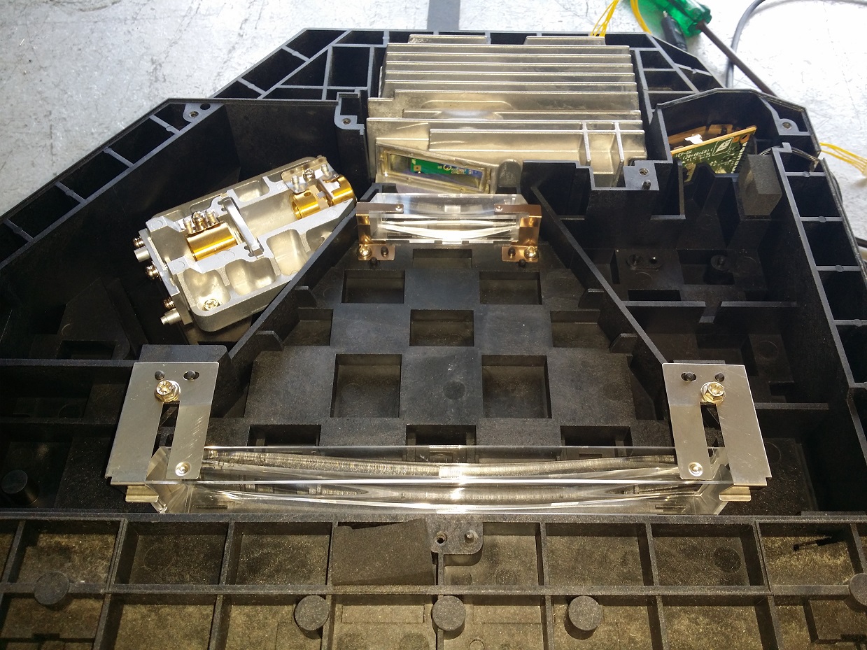
But before I got that working (I didn’t expect to) I also pulled the entire assembly out of a large office printer to get a more standard module:
Unfortunately the lenses are likely to be UV-opaque, so they have to go. Might have to investigate milling/polishing new lenses from a UV-transparent material, but that’s a big job for a later date. It also has a laser diode mount/focus assembly (the IR diode has been removed) and a sensor to synchronise against the start of a scanline (probably needs to be replaced with something UV sensitive too). The polygon mirror is in the big sealed metal case at the top (good for keeping out dust!). But the whole thing is really big and heavy, and might only be useable on a large gantry.
See also this project on hackaday.io, uses a laser printer polygon mirror and I think blu ray laser if I remember right? I salvaged one of those mirrors and an Xbox laser to try it too, just didn’t get around to it, I’m interested in what you come up with.
Main problem with this idea if the f_theta lens it tuned to keep a 1000nM IR laser focused to a nice spot across the 30cm scanning area. This means your laser spot will shrink and grow from side to side.
I have not seen anyone get this done and achieve the same quality of result that you can get with a $50 inkjet printer and some proper trannies. (except on a small area where the focus can be maintained)
Agreed that toner transfer can sometimes be less than fun
Please do build this. It would be awesome to be able to skip the tranny step. Just as long as you are aware that the result probably wont be as good as using a tranny.
Oh - the other thing to remember - photoresist is low contrast. corona around your laser spot is not a good thing. That is the big problem people have trying to directly mount a blue-ray diode to an X/Y table.
I’d also try adding a fine physical slit somewhere in the optical path to block most of the diffused light, although adjusting that might be tricky. Simplest/most accurate might be a printed transparency.
I looked in my member storage box and found a third polygon mirror that I must have salvaged a year or more ago… It’s got 12 facets, so it’s probably a little fast for my purposes. That and when I span it up it took over a minute to spin back down naturally!
I need some way to determine the rotation speed of each of these mirrors, which was going to be a laser pointer and a photodiode hooked up to the scope (neither of which I currently have), but an interesting alternative just showed up on Hackaday. Connect a function generator output to a bright LED and you get an adjustable strobe light. Set the strobe frequency to freeze the motor motion and that gives you the revolutions per second!
They do, but that’s not what I’m concerned with at the moment. I have literally no idea how fast these motors are scanning, and that will affect how fast I need to be able to drive the laser diode and what effective resolution I might be able to get. So I’d like to characterise the modules I have before I make any design choices.
The final device will have an optosensor to determine scan speed and offset, as I’ll need both to properly time and scale the line data.
I characterised the 12-facet mirror last night, which took a bit of effort. The function generator doesn’t really allow me to adjust the frequency finely enough, so it was fairly tricky to get the mark on the motor bearing to freeze. Also, the duty cycle of the output is pretty large, so the mark was blurred even when stationary.
Anyway, I measured the rotation at 296Hz. With 12 facets that means it scans a line about 3552 times a second. Which is probably way too fast. This one has an internal clock unlike the others (which is why it’s the first one I did this test on), but the datasheet gives the possibility of either passing in an external clock, or modifying a divisor to change the speed. I’ll probably go with the external clock just to make the design common to all the modules.
It’s pretty dim even with the current cranked right up, but it’s enough to play with the optics until I’ve got a stronger laser/driver combo going. I can get a very sharp pinpoint focus at the scanner output window, although it doesn’t show up well on camera: https://goo.gl/photos/uXFNvjWVTYSRuqvQA
Removing all but the first lens gives a sharp point at the output, but as it produces a large circle at the scanning mirror, most of the laser light misses the mirror entirely. Adding the second optical element produces a rather twisted light path - the laser light focusses into a horizontal bar at the mirror, then the beam diverges and refocusses into a vertical bar at the output plane. Most of the light still goes somewhere unwanted, but it at least it all makes it out of the scanner. Adding in the two oblong lenses gives me back a sharp point! It’s not as good as it could be because the lenses aren’t designed for this wavelength, but it’s still better than I was expecting.
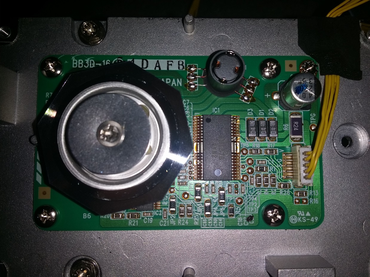
I got the datasheet for the optical sensor on the side of the assembly (http://docs-asia.electrocomponents.com/webdocs/0d1f/0900766b80d1f955.pdf). It’s only 30% sensitive to the 405nm laser wavelength, and my dim laser didn’t trigger it even when focussed right on it. But there are two gain resistors on the board that I changed from 4.7k to 33k, making the sensor much more sensitive and now it produces a signal pulse when I get the laser on the right spot. Unfortunately when the beam is scanned it’s still too dim to get any results even when the mirror is spinning slowly, so that’s another item to wait until I’ve got a better laser module.
I got some cheap 20mW 405nm laser diodes off Ebay to replace the dim one I started with, and the difference is staggering. It’s pretty obvious now that I wasn’t actually getting the old unit to lase at all, it was just in the far dimmer LED emission mode that exists at low current. The replacement diode behaved similarly, staying dim until I got above about 70mA at which point the unit started lasing and the brightness went up exponentially.
It’s bright enough now that even with the mirror scanning the beam, it creates a visible line on the non-fluorescent benchtop, and a very bright line on fluorescent materials like white paper or the glow-in-the-dark paper I also got from ebay for testing purposes. I’m hoping to use the glow paper to create a persistent image of the exposure when the system is more complete for testing.
There’s a lot of reflections happening in the optical path for the large scanner unit; the optics have non-reflective coatings but they’re designed for IR. This has convinced me to go with a much simpler setup like the OpenExposer, with a single first-surface mirror.
I’ve scavenged an old USB scanner from the boneyard to act as a Y axis; as the sled requires the glass to remain square, I’ll use magnets on it to drag a PCB carrier above the glass. I can either use the existing hardware to drive it over USB (it’s fairly well documented and code is available in the linux SANE codebase) or just solder in a separate stepper driver.
It was a random office photocopier that had been pulled apart, I couldn’t possibly remember what it was. And the polygon mirrors were all unlabeled. Sorry!

 It’s got 12 facets, so it’s probably a little fast for my purposes. That and when I span it up it took over a minute to spin back down naturally!