My motorbike never came with hazard flashers, which is something i’ve found myself wishing i had a few times here and there.
Many moons ago this guide was posted for a hazard flasher mod: http://www.triumphrat.net/tiger-800-800xc-mods-and-workshop/228868-mod-hazard-flasher.html
But the images are gone to time. Although this person on page five put up some pics of their own install: https://www.triumphrat.net/tiger-800-800xc-mods-and-workshop/228868-mod-hazard-flasher-5.html
I’ve idly had this project on the backburner for ages but with a lot of work on the bike lately I figured I’d get it done.
I first condensed the instructions into this text:
For those of you who have OEM alarm installed, you’ll find some connections coming out from this connector, but for those who haven’t installed the alarm, this connector has only 2 loops of black cables.
- Remove and unplug the alarm connector
- Insert a cable through pin holes #7 and 8 (they are numbered on the side of the connector)
- Place a fast-connector to the end of both cables, and reconnect the alarm connector ensuring the cables we’ve just placed, do contact pins #7 and 8 of the female connector
- Place the connector back and leave it there for the moment
- Route 2 cables from the front part to the rear part of the bike:
- Now plug these cables, to the alarm connector we’ve created and waterproof it.
- Tin solder 2 short cables to the diodes (use the grey marked leg of the diode) + heatshrink
- Tin solder both diodes to a long cable + heatshrink
- Remove the topcase support, loosing the 4 #8 hexagonal bolts to gain access to the turning lights relay
- Loose the relay. We can see 3 cables coming out from the relay (2 orange-browns and 1 green-brown).
- Connect a long cable to the green-brown cable (don’t touch the orange cables), using a fast-connector (no need of peeling nor cutting any cable!).
- Place the relay back to its original position:
- Now route both cables (the alarm-diode cable and the relay cable we’ve just prepared) and connect them to the handlebar switch
And over a few readings i’ve kind of scribbled together this diagram, which also includes me figuring out the internal wiring of some illuminated switches I have:
I am going to use the switch I’ve drawn in the lower right as its newer (not discontinued), hasnt been in the weather, the illumination is better cos its led rather than incandescent etc.
I’ve got some 1N5400-TP diodes, 50v 3a for the circuit.
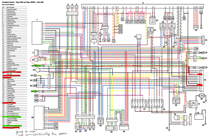
I’ve also got this scribbled upon diagram of the bikes electrical system, the brown wire to the relay above is electrically the same as the bright green wire labeled on 67 in the diagram:
So I ask the brains trust this, that I need help to figure out if my assumptions are right, and what a final wiring diagram would look like. I would like the switch led to flash alongside the indicators.


