I do a decent amount of work at the space on my Electric Vehicle, a Blade Electron MkV/R on which I did a show-and-tell in May. I thought I should start documenting this work somewhere partly for my own records and partly for others to see, so I’ve been photographing stuff to upload here at a later date. Today is that day!
My battery management system (an Orion BMS) was reporting that one of my cells was on its way out, claiming it could only store 50% of its rated capacity. I wanted to eliminate all other causes before I blindly replaced it. I knew the BMS was likely correct that something was wrong, but I wanted a second opinion (and more information to help work out if it just died naturally or something else killed it). The BMS samples at only 10Hz and I wanted something a little quicker to check for voltage spikes, and by spike I mean 0.5V above normal. I tried using an oscilloscope but we have no logging oscilloscopes at the space beyond a trigger logger and I couldn’t get the trigger to work at such a fine level, no battery-powered oscilloscopes so I would’ve needed a 240V inverter, and hacking together some longer probes so they’d reach from inside the car to the battery terminals didn’t work. So instead I used an Arduino with xoscillo connected to my laptop, which let me sample & record with 8-bit/0.02V resolution at 59KHz. Good enough given the low cost of $0 in parts I didn’t already have.
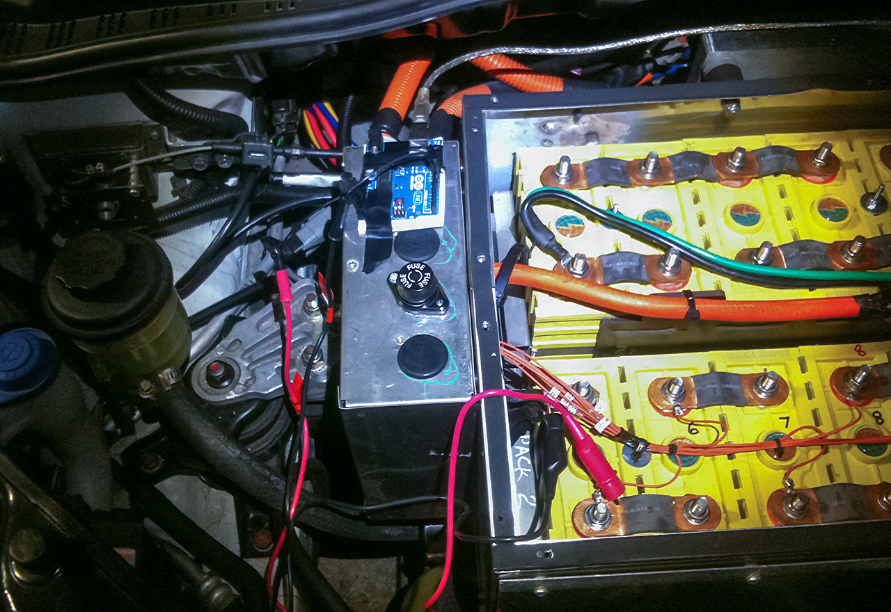
Arduino taped to the relay box, probes connected to cell 41 in the lower left. This is also what I was doing in Geek Shirt #27!
I went for a drive with @theban who helped record the data while I thrashed the motor. Analysing the 7.9 million data points we recorded, I determined two things:
- the battery isn’t as dead as the BMS said, but it is definitely weaker than the other cells. BMS was wrong as I expected, but not completely wrong.
- There’s some high-frequency ringing on the voltage heading into the battery, and constant voltage oscillations would shorten the battery’s lifespan. This is the first cell attached to the cable that connects the front battery bank to the rear battery bank. Such a thick cable that’s fairly long carrying so much electricity at constantly-changing rates, there’s likely some eddy currents being induced. This seems like the most plausible explanation for the curves on the graphs.
Solution: my BMS can actually use the sensor wires to correct for part of this by shunting around voltages and I can add some filtering components, but it’ll take a lot of calibration to get it perfect. And it’s best to start with all cells equal. Just in case one of them died, I keep a spare Lithium battery from the same manufacturing run in the car so it’ll be exposed to the same conditions as the other batteries and drop-in compatible, but without any cycling it’ll always be healthy. So it’s time to swap some cells!


