So, here begins the journey of cleaning up the giganto CNC and breathing some new life into it. (Wiki is broke so this will be the makeshift info page)
General information
-
Signal voltages
-
Step + direction signals: These originate from the parallel port breakout board, and require level shifting to 24V (HTL) for the LUST motor drivers. (other option RS422, chose HTL due to simplicity)
-
Enable signal: Each of the motor drivers have an enable pin, 24V active high (internal power supply).
These will be run to a 3 pole relay in the control cabinet, triggered by the parallel port board (enable signal enables all drives). Unless a 5V coil relay is found this will also require level shifting. VFD may or may not be connected here too.This may end up being permanently pulled high, as there is also a start input required (may be automatic, turns on the drives power stage) and an emergency stop input to engage the brakes/decelerate the motors. -
VFD speed control will be a 0-10V signal from the parallel breakout board.
-
Mains voltages:
-
240V: Due to the wiring available at our 3Ø outlets, there is currently no 240V available in the control cabinet (no neutral). To remedy this a 240V inlet socket will be installed, to separately power any 240V gear (computer, power supply etc). This is undesirable as if it’s unplugged when in use, bad things will happen. A contactor may be installed to ensure both supplies are present when in use.
-
Power supply
-
The original LAMBDA supply had some weird enable interface that was becoming a problem. Instead a Boneyard supply has been used, with 5, 12 and 24V rails. These have an unknown current limit however it should suffice.
-
This will power a majority of the control gear: parallel interface board, level shifter, control relays, motor brakes (through LUST drives)
Todo
- Far too much. That is all.
- Troubleshoot interface/settings of LUST drivers
- Determine inputs for LUST drivers, enable, start and emergency stop? (see enable signal under general information)
- Terminate the endstops to a terminal strip for further use.
Components
Motors
- X axis: Transtechnik SM 100-50-030-P0-45-R1-B1
- Y axis: Transtechnik SM 100-40-050-P0-45-R1-B1
- Z axis: Transtechnik SM 100-50-030-P0-45-R1-B1
- Spindle: Perske VS 50.09-2
Drivers
- 2x LUST CDD.34.003.C2.0
- 2x LUST CDD.34.005.C2.0 (1 spare)
- Telemecanique Altivar 31 VFD (spindle control)
Power supply
- LAMBDA Vega 650
- Unlabeled boneyard supply. 5, 12 and 24V out.
Proposed components
- Parallel port interface: http://www.ebay.com.au/itm/USB-DB25-Interface-5-Axis-Breakout-Board-for-Mach3-CNC-PC-Stepper-Motor-Driver-/390994555093?roken=cUgayN
- Level shifter: https://www.sparkfun.com/products/12009
Documentation
- Lust DriveManager: http://www.lt-i.com.tw/files/DRIVER/201005280040341.pdf
- Lust drivers: http://drives.lt-i.com/lti-download/pix_download.pl?idx=26792
- Transtechnik motors: http://www.barr-thorp.com/wp-content/uploads/2011/06/PacDrive-SM-Motor-Operating-Manual.pdf
- VFD programming manual: https://stevenengineering.com/tech_support/PDFs/45ATV31PM.pdf
- VFD installation manual: https://stevenengineering.com/tech_support/PDFs/45ATV31IM.pdf
Wiring diagrams
-
Pinout/wiring for motor to driver. This isn’t an ideal setup, but it works so I’ll let the sleeping dog lie.
-
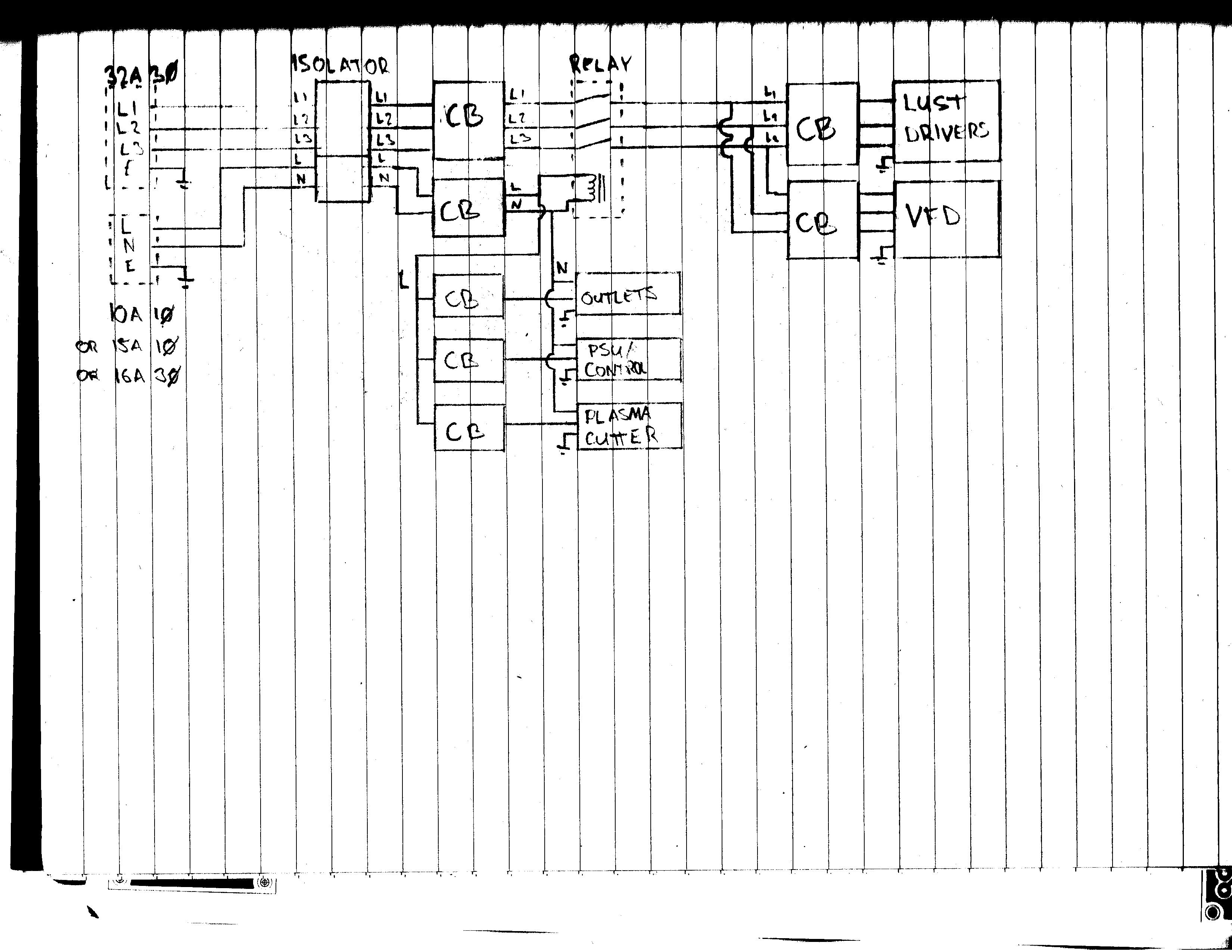
Potential mains wiring diagram.
Relay to disconnect 3Ø supply if 240V supply is interrupted.This might be a bad idea, possibly better to tap into e-stop signal to LUST drives - active low, so run off 240V/24V PSU? Circuit breakers for VFD, LUST drives, 240V outlets, control gear (PSU) and welder/plasma cutter. If adding capacity for plasma cutter, 240V may have to come from a higher current 3Ø (16A) outlet, if a neutral is present at said outlet. Probably going to overload a typical mains outlet with it.

Build log & thoughts
15/4/15
Will attempt to drive the servocontrollers with some manner of external multivibrator. The operation manual mentions the time response of enable inputs which may have to be considered, however the start control isn’t being used implying that’s not very important. Also worth putting a LED on the reference reached output pin to see if it thinks it’s done. (4-36 application manual)
24/2/15
-
The level shifter was constructed and connected. However, due to the nature of this circuit a voltage divider is created with the 1/1.2K pullup resistor (turns out these get a bit warm, dropping 24V) and the 3K pulldown in the LUST drivers. At present I’m not sure if this is a problem, but the drives specify a control input voltage of <5V for low and >18V for high. The voltage divider created hits ~18V, however the drives to seem to recognise this when checking the input states of the pins.
-
The kiosk has been reformatted with Windows 7 and had Mach 3 installed. Currently this appears to be producing the output signals required, and the drives have responded to the direction signal (using step/direction), however the step signal was largely disregarded. At present I am under the impression this is just a setting that’s wrong in the drive. It is also possible the step pulse isn’t enough to get over the 18V threshold, however toggling the pins on the parallel port manually had the same lack of effect. Next step will probably be hooking the function generator back up to the driver to get a nice clean 24V squarewave for step input and fiddling around with the settings from there.
-
Lastly, the power supply was swapped to a boneyard find as the initial LAMBDA supply was giving @Hally and I some grief with finding the enable input. No specs/model on this new supply but it seems to do the job so far.
16/1/15 18:26
- Hobbytronics design seems best. Will make our own version with 6 channels, along with two relay driver channels (enable and a spare).
14/1/15 19:20
- Will use the parallel port driver thing. Gotta find something to do 5 to 24V level shifting. Might have to rig up some boards with MOSFETs and resistors and magic.
This will be edited to update content.
