HP 9810 Calculator Repair

Hi all,

A few months ago I went to use my calculator and to my horror it didn’t work. It powered up but the keyboard was unresponsive and there was nothing on the display. :frowning:

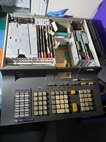
Full of hope I opened it up and had a look inside to see if there was anything obvious; re-seated all the boards, etc, but no dice.

I do have a lot of documentation including full schematics, a third party repair manual and a full emulator (in java). So I dove in and started reading. There is no processor in this thing as such, it is ALL discrete logic. As such I had the blessing and curse that I had to work in the micro instructions (i.e. smaller detail than assembler!).

Getting to work I spent ages orienting myself. I wrote up proper card pinouts for the edge connectors (marrying up the names in the repair manual with the names HP uses), printed out a heap of references and identified all the cards. This resulted in many many printouts, excel spreadsheets, etc.

Still full of hope I poked around with the oscilloscope to see if it was an easy fix. Hmmm, the display enable signal is always off - Ah Ha. Tracing this back sent me down a rabbit hole and I hit the limit of what I could do with the oscilloscope.


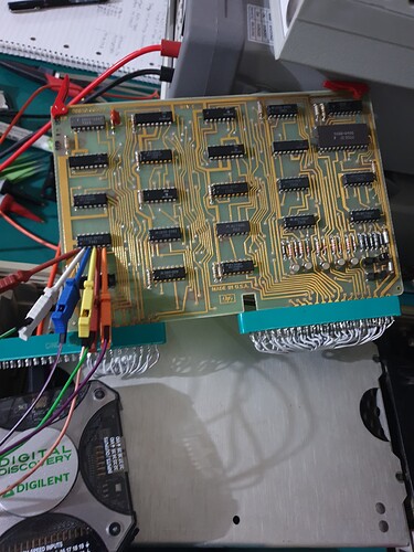
I needed a logic analyser so I can determine what micro operations are being run. Fortunately the ‘processor’ card has a test connector that outputs the number of the instruction that has been read from it’s ROM. From this I found it is in a tight memory read loop.

After muck more mucking around, reading, testing, replacing IC’s, more testing, etc. I got to the point that I found that the main ROM’s were not outputting any data. I re-checked that poweer suppoty as I thought maybe the -2.4V boas was not right as the -12V supply was a little off. It was in spec but, I spent a while chasing that down. I finally replaced that card (of 2 power boards) with a bench power supply but that made no difference; red-herring.


After a lot more work (and several trips to jaycar to get 74 series logic IC’s) I now have ROM output as well as some activity on the keyboard as well as the display!!! It seems that a lot of the IC’s on the memory controller board were at fault. I had to change from the logic analyser to the oscilloscope a few time as some IC’s were outputting non-binary signals.

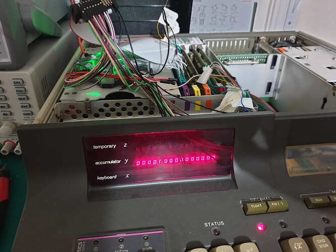
It is still not fixed as the display is still erratic and it is not responding to the keyboard properly. But it is finally some progress!

Time for a victory beer before I get back into it…
1 Like

Time to get back into it. I knew the ALU1 was not right so I re-tested to make sure and sure enough outputs 0 and 1 were dead no matter what the input.

The ALU is, of course a static ROM and the chances of getting another is pretty low…except that I do have another unit. But the ALU card on that one has a bit of tape on it that says ‘dud’. What are the chances of the ALU1 bine the one chip on that board that is broken. Well it turn out the chances are high! :frowning:

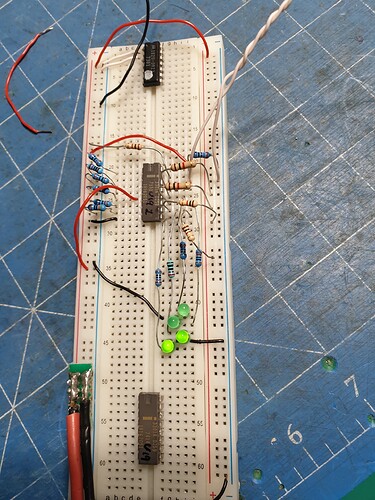
I pulled them out and tested on a breadboard and sure enough I can replicate the error. In this photo all LEDs should be on with this address.

So with both ROM’s broken with what seems to be the same problem, it looks like I will need to build a replacement.

I need to find a parallel EPROM or EEPROM that can work at 8MHz and can be easily programmed…

The good news is that I do have the full contents of the ROMs.

1 Like

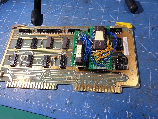
After Much stuffing around I now have a test replacement ALU:

Getting a EPROM (or any type of ROM) that is fast enough and is supported by my programmer is a HUGE challenge. They are hard to find, and they are always either out of stock or ridiculously expensive.

I do have a small supply of some I have recovered from various photocopiers, but they are mostly too slow. The few that are perfect for the job are not supported by my programmer.

But I do have just the one that fits the bill.

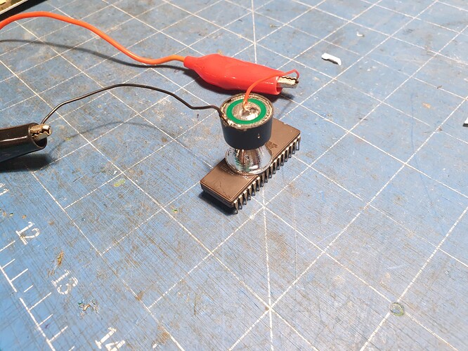
The crap UV eraser I got failed after one minute of operation. grrrrrr. So I tried with a UV LED from a COVID test kit. Yes it is not the ‘right wavelength’ but these tings don’t put out just one wavelength they spit out light across a band. So there is just enough of the right wavelength to eventually get the job done if you put it really close and concentrate it.

Some test EPROMS took 2 hours to wipe. But the ‘good’ one ended up taking about 18 hours!

Anyway I got it in and it works.

See the bottom 4 signals. Previously ALU D0 and D1 were always low. The fact that they are not doing much here is not necessarily a problem as they feed into the other ALU ROM. What are the chances of that also being stuffed?

This fix, of course, has not resolved the overall problem, so still more work to do!

1 Like

Sitrep: I think the processor and ALU are now working. Pretty sure the memory is working as well as I’m now seeing it go into the memory refresh cycles. However it is still not displaying correctly on the screen nor responding to input.

I replaced the ALU and BCD ROMs with ones I recovered from a photocopier

I ended up being able to write to all 6 of the fast EPROMS I have. In the writing software I found a chip that has the same number of pins and was as similar in name as i could find. So I now have lots of usable EPROMS (Ignore the non-volatile SRAM).

The next problem is that I need to put this card back in its slot so I can use my riser cables to diagnose the IO Register card. So I’ll need to re-do these, oh so elegant, ROM fixes to be much lower profile (or possible move them to a remote location).

1 Like

All right, my PCB’s have arrived.

I still need to remove the sockets on the board so I can solder these on. They will then be just wide enough. But it does look a lot better!

1 Like

Now that the ALU and BCD is fixed (hopefully) I can see that the CPU is working. It is even pausing to do memory refreshes. Good signs.

So I turned my attention to the IO Register board. But, after much mucking around, I can’t see anything wrong there. It is outputting data as expected.

I then moved onto the display board. Tracing the data input (well D0-D3) I could not see an issue there.

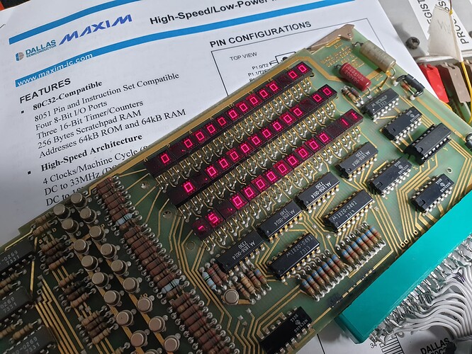
I noticed that whenever it tried to update the display that all three lines (X, Y and Z) are momentarily updating. So I looked at the data input that selected the display rows. The first part of this is to invert the signals. Then I saw this.

The Z row is always being pulled low, so this is overriding any other update. We have a bad 7404! And I even have one of those to replace it!

I whipped it out and whacked in a new one. It is not full y fixed now but it is a step further. I can get much more coherent output now and some of the other functions almost work.

1 Like