So some of you might have noticed the new interlock on the table saw and wondered how it came about.
The current interlock has taken a little bit to produce and is based on advice and support from multiple members, including but not limited to @capella_ben1@doc@Thermoelectric and myself.
Its guts consist of:
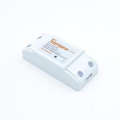
A modified sonoff TH16, which looks like this:
A three-phase contactor
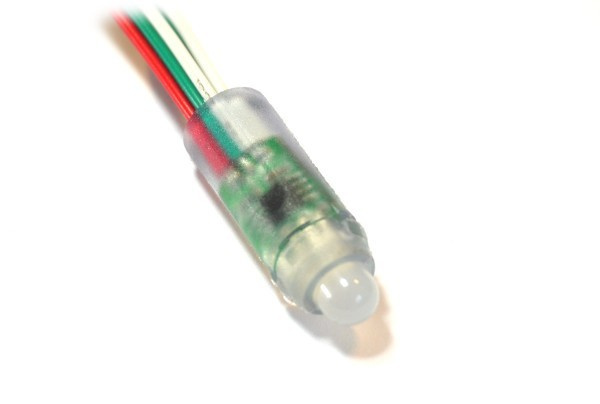
An addressable led
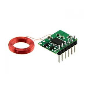
An RFID coil and reader
All of those things crammed together inside that little box looks a little like this:
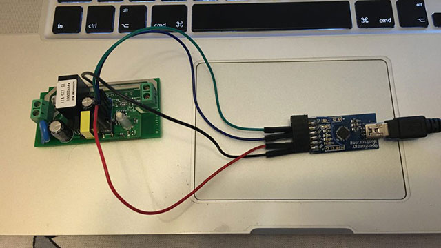
First up I popped open and modified the sonoff to add headers, like so.
Then once I had the headers on, I tested that I could use the addressable LED on the single GPIO pin I could use on the board (GPIO14).
I tried to test the RFID reader but interestingly it wouldn’t power up. It turns out the 3.3v output on the sonoff was outputting 3.2v when the board was powered. This was enough for the board and the esp8266 (it only needed 3v) but the RFID coil no likey that. So I ended up soldering a cable onto the 5v-3.3v regulator where the 5v came in.
Then, some appropriately trained electricity gnomes wired it up and I threw some test code on the sonoff to see if it would turn the contactor on and off.
I purchased a hall effect AC current sensing board but it’s tiny and there’s shit all isolation between the 240v side and the chip. So i’m currently looking into implementing a current transformer setup like http://www.the-diy-life.com/simple-3-phase-arduino-energy-meter/.
Buut the sonoff th12 only had one GPIO pin and so I’m going to be moving to using a Sonoff TH10 which looks like this:
This way I can break out both GPIO pins (via a built in 2.5mm 4 pole audio jack) and use one for the status light (like I was previously) and the other to read the current transformer state. Except neither of the GPIO pins broken out (GPIO4 or GPIO14) are the analog to digital converter on the esp8266.
To work around that, I’m designing a PCB to take the cables from the 4 pin audio cable, have a plug for the status LED on the lid and then either an attiny85/attiny13a/comparator IC to turn the analog voltage from the current transformer also onboard into a digital on/off signal depending on if the tool is in use.
I hope to update this thread soon with a resolution to the current transformer testing and then plan a budget and working bee for us to build one for each tool we need