Thanks for the comments.
@denominator
I can only imagine how it will work and the engineer in me wonders if it will ever be practical.
The good thing is, it’s a proven circuit; Pelrun has one on his Prusa i2 at the space at the moment.
IR is excellent for object detection its just not good for distance
measuring. In industry we don’t use IR for really accurate things
because IR sources are everywhere from fluro lights to the big ball of
fire in the sky. One way to stop this would be for the led to transmit a
code so you know if it is your light source. You could transmit
different signals for each of the leds so you know which one is
triggering them.
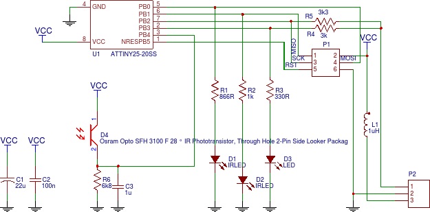
That’s exactly what the ATTiny does; the two IR LEDs are alternated, and a “blank”: period allows adjusting for ambient conditions to be measured. The resistor choice is about presuming they hit at about the same point on the bed (easy) but take different lengths (easy; offset, angle and SOHCAHTOA ) meaning that at a particular distance the intensity at the receptor is the same (slightly less easy)
In the PCB above (and I apologise in advance for the slavery units) the emitter or the close LED is 0.4in from the phototransistor, and the emitter of the far LED is 0.6in. The close LED is at 45deg and the far is at ~35deg.
At roughly 0.2in above a reflective surface, the near LED will travel just under 0.57in
At this height, the far LED will travel 0.89in. The ratio of the two is 1.56:1. They will both be reflected at the halfway point, and have proportionate losses that muck up the maths, but bear me out.
If we want the two to hit the phototransistor at the same intensity and presume perfect reflectance (an incorrect but useful assumption) and we use the inverse square rule, we need the far transistor to emit at 2.43 times the intensity (1.56 squared).
Chosing a convinient starting point, such as forward current If = 20mA we can use the charts in the datasheet (pdf) to find another curret that gives 1/2.43 (i.e. 0.41) times the emmision intensity.

Of course the bed isn’t perfect. I can’t easily recall / google whether the loss of light on reflection is linear or not. If it’s linear, at the desired distance the beamlength ratio will be the same to and from the point of reflection, so the point of equal intenisty should be the same.
Because of the inverse squareness, the narrow half-ange (9degrees) of IR emissions, and the logarithmic responde of the phototransistor, there is a very rapid fall-off of the far beam intenisty if we’re too far, and a very rapid gain on the near beam intensity if we are too close (until we go outside the beam, where it drops off again, but we will also be outside the beam of the far LED too)
You have used resistors to limit the current, the resistance will change
depended on temperature. It could ether go up or down depending on the
material it is made out of. Probably the longer you run the led the
darker it will get. A constant current led driver should solve that
problem.
After making my poor head hurt (although not as much as when trying to understand MRI sequence and phase encoding; at least we’re sticking with real numbers and out of k-space here) I’m going to start with the values that work for the original board and then consider fiddling.
I thought of a constant-current source (e.g. through an opamp) but it pushed up the BOM and would require making modifications to the basic circuit; that will have to wait for a proven need and v0.2.
I was also including the voltage drop out of the ATTiny in calculating resistances.
As for temperature; the current at 9-20mA for a voltage drop of about 3.6v is relatively small, well less than a 1/8 watt. The environment will be an issue (I.E. hotend distance) but given other components are tolerant to about 85 degrees, that will be the maximum envelope I’ll have to think about. Thanks for making the point.
Thankfully the emission intensity is relatively linear to forward current in the range we are looking at, thus the ratio of intensity should be preserved if the resistance increase is relatively linear, so hopefully things will even out? I could presume the intensity will be lower, but we’re looking for a similar intensity rather than absolute intensity (differential comparison rather than absolute value)
@nogthree
Hey Lauren,
I’d be interested in one or two of these, I’ve been following with
interest people using DC42’s design and currently use FSRs on my delta.
I’ve go about 10 boards coming and parts for about 4; the key components are;
- ATTiny 25 or 45 SOIC-8
- 1uH inductor
- OSRAM SFH 3100F (RS-Online 654-8738)
- OSRAM SFH 4141 (RS-Online 876-8741)
- some resistors (0603), an optional 0603 status LED, and some 0.1" headers
Of those four I’ll probably kill 2, so the other was for the space. The PCBs were earmarked as follows;
- as many as it takes forme to make one working one for me; parts for up to 3 space printers
- 1 or 2 for Pelrun to make / kill
- 2 or 3 for the printers currently at the space. If I don’t kill too many,
The rest are first-come-first served.
As an aside, there is a silkscreen error sent to the fab; free PCB to whoever picks & posts the inconsistency here first 
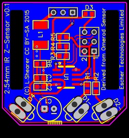


 must be my fault.