I made a clock
My first completed project of 2014!
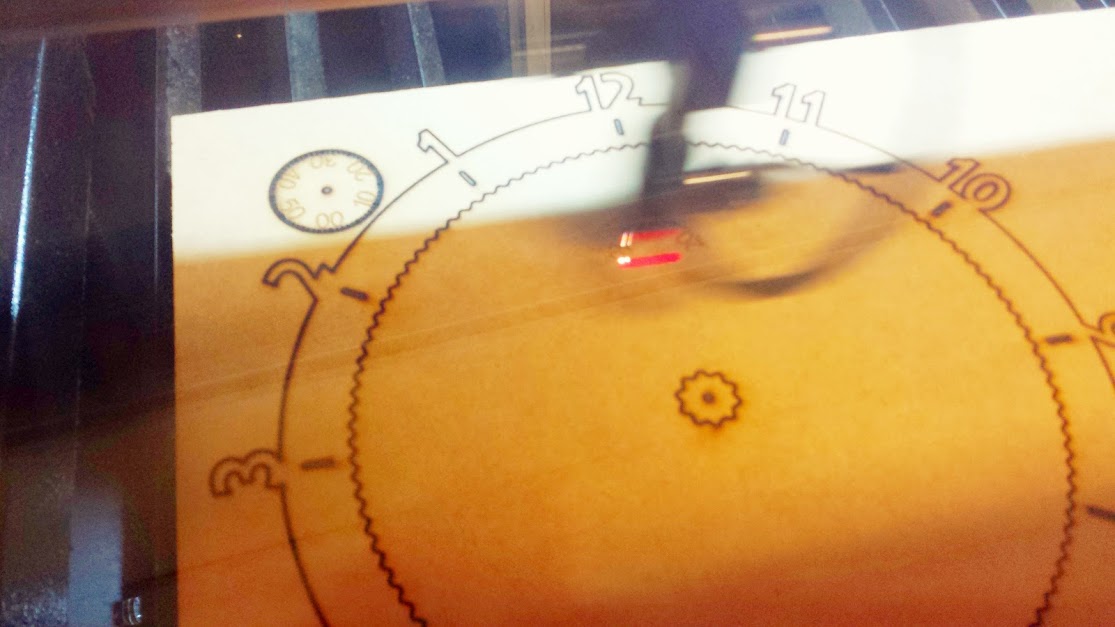
You are probably now aware we have a fancy new laser cutter, and I wanted to try it out. I grabbed this thing off thingiverse and shoved it in the laser cutter. Obviously power, skill and timber were also provided. If I recall correctly @buzz provided the skill.
It took a few passes on the laser cutter, $2 worth of laser time, because i have the settings a little low for the thickness of MDF i was using. A part form that it was an easy cut. I will look at making this again in Acrylic to improve the look.

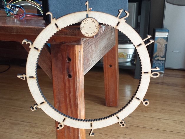
This is the Gear O’clock in all its glory. As you can see it is quite easy to tell the time 12:55. I was surprised, before i built it I thought it would be difficult to tell the time in such small increments.

I have had the parts for this project for 3 years. Like any good hacker I have been hording electronics and stuff for quite a while. It feels good to finally complete a project with some of this junk i have been collecting.
Down to the build
Basically you slap the cog and its fun number wheel on the end of a stepper and get that guy turning. And that is the whole clock b̶u̶i̶l̶t assembled.
…with the exception of the electronics and code
I had some fun with the stepper motor. The stepper I have been using has 512 steps per revolution (it is geared down). I recommend it as It can be run from 5V and is definitely powerful enough to deal with the inertial properties of the clock wheel.
The challenge is, whatever increment you would like to move your clock you have to divide 512 to do it. But 512 is not nicely divided (a whole real number ‘no fractions or imaginary numbers’) into 1 5 or 10 minute parts. I decided to move the clock in 5 min increments (to save power) which means 512 / 12 = 42.666 not cool math. not cool.
This is easily fixed in the code by moving the stepper 43 ever 5 min and correcting error in the steps by only moving it 39 steps for the last 5 min of each hour. (43*11 + 39) = 512
I ran the code on an arduino uno R3 to test everything out before moving it to a $3 pro-mini clone (mega 328P 16Mhz).
I have quite a few of these guys so hit me up if you would like one before the electronics vending machine is up and running.
The arduino is powered by a battery through a variable switch-mode voltage regulator. They are quite cheap and very efficient compared to step-down regs. The power can be a little noisy but isn’t too bad if you throw a couple of capacitors in there.
The battery power is connected to directly to the stepper through a stepper motor driver chip. To save power the code turns the enable pins on the driver chip off while the motor is not turning. This effectively cuts the power to the motor. There are almost no forces on the stepper so it wont loose its place. (I think 3D printers and such will leave the power to the motors on the whole time so they don’t loose their place/position accuracy and ruin a print)
The aforementioned code queries a RTC (real time clock) for the time. The RTC will keep time even when the arduino is not powered.
Most work from on Unix time which is weird, interesting and I hadn’t realised before this project. derp.

XKCD
My clock will only work till 2038 and then might run into some troubles.
The RTC is asked for the time every 10 seconds and the code checks to see if 5 min has passed then moves the motor. Very ugly code but it works. As @buzz says, ‘it may be horrible to look at but it works and it is documented’.
Power saving is a massive issue with this clock. The enabling and disabling of the motor helps quite a bit. I need to include a watchdog timer enabled sleep mode which effectively turns the micro controller (Arduino) off and it wakes it self back up again to check the time every 8 seconds. 8 seconds of power down doesn’t sound very impressive, but that is about 1/9th of the power usage of being on the whole time. Another way to say it is that the clock batteries will last roughly 8 times longer.
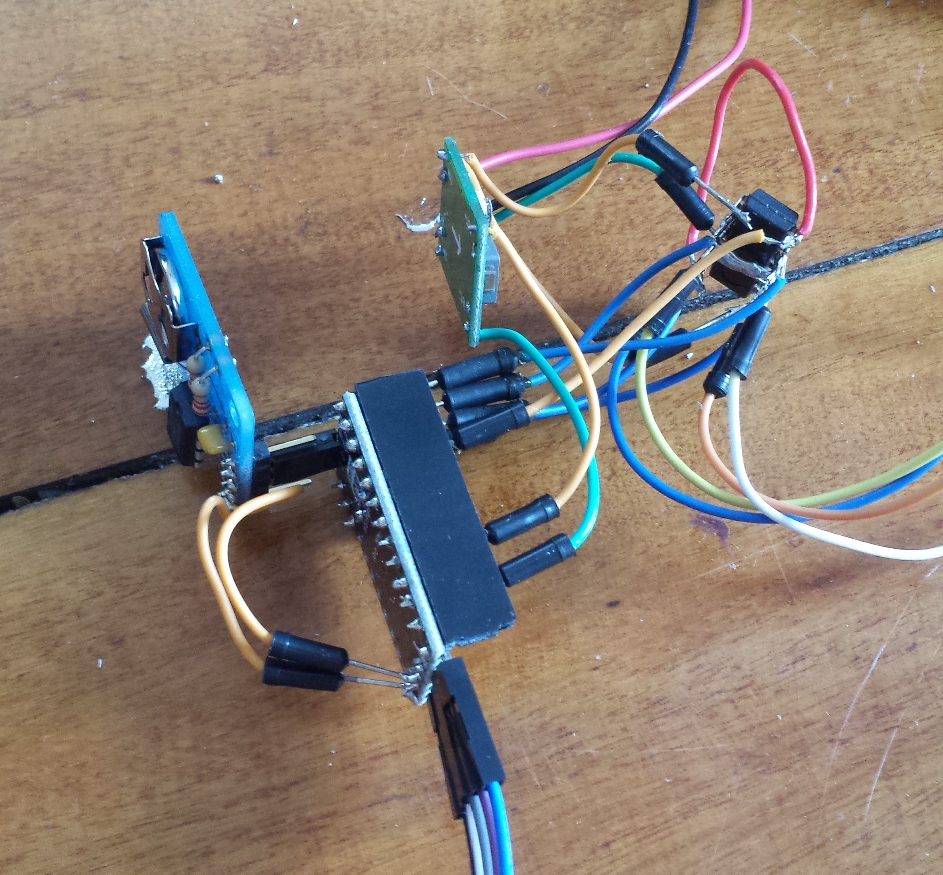
This functioning mess or wires sorely needs proto board and an enclosure. The RTC is on the left, micro/arduino in the middle, power regulator top and stepper motor driver on the right.
My next step will be to cut this again out of Acrylic and improve the code. I should probably also add some buttons to change the time and adjust for stepper drift.
Congratulations you made it to the end of my babble.
I’m happy to help anyone with making the same or a similar project.
Hally

