Hi all,
I’ve been working on a small music synthesizer toy for a teenager who was born with severe mental deficiencies, leaving her with the approximate motor skills and intelligence of a toddler. The music toy here just plays tones when buttons are pressed and flashes a LED string, but I’m considering ways in which this can be expanded to try and help improve motor / mental skills.
It is worth pointing out that there is nothing like this commercially available on the market. Not to parents of said kids, to physios, schools … nobody is making these things. There is an opportunity here for Brisbane Hackerspace to perhaps make a small production run (~10) of these prototypes so that the idea can be more thoroughly tested out.
The first revision of this used an ATTiny85 and originally was based on some code I had written for a bicycle horn/bell… but this code was found to be too inefficient on such a small MCU, and the lack of pins on the ATTiny85 was a real problem.
The ATTiny861 has been used in this latest revision, with the synthesizer code itself loosely modelled on the famous Commodore SID chip. The code is capable of polyphonics with square, triangle and sawtooth waves, and the MCU can handle up to 8 channels.
Naturally, the synth code is not restricted to this application and can run on other MCUs for other applications. There is a port of it to AMD64 Linux for example for testing purposes.
The code occupies most of the device’s CPU time, but only about half the flash space and there’s possibly another hundred or so bytes of RAM for program state, so there is room for expanding this into a “Simon Says”-style toy or interfacing it to a larger MCU such as an ESP8266 for interfacing to a smartphone application.
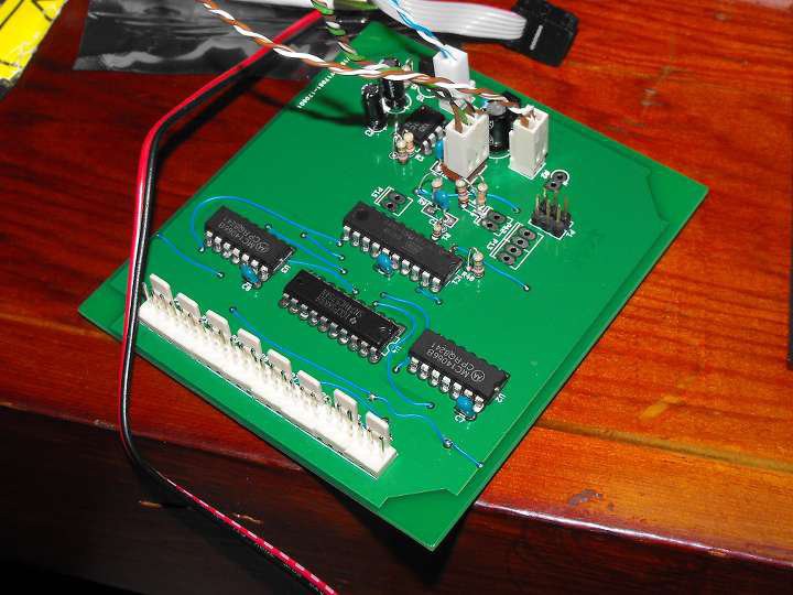
Main board layout:
Main board schematic:
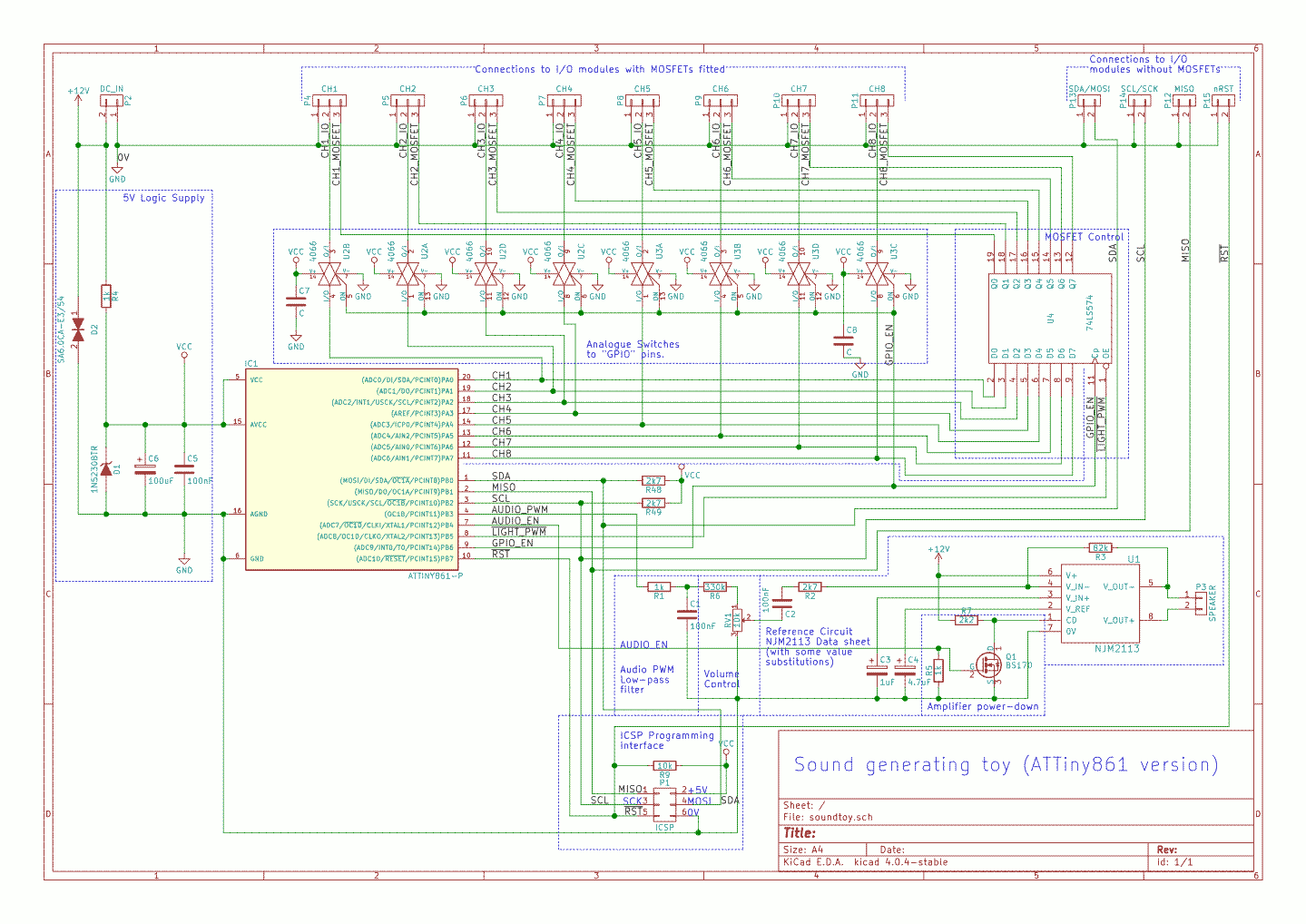
Latest version uses a 5V LDO reg in place of the zener across the MCU VDD/GND pins. Basically I use the port A pins on the MCU both for selecting LED channels for PWM control via the octal latch (74HC574) and for input via the two MC14066s
I/O module schematic … one per channel:
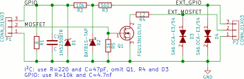
The idea here is that the board can survive accidental or deliberate shorting of the GPIOs to +12V or 0V and handle ESD. I’ve since found that the TVS diodes used are not ideal for this voltage, but in general, things work quite well.
Firmware:
The device in action:
Gory back-history on the project for those interested:
At the moment, the ADSR waveform envelope for a “voice” also controls the brightness of the LED string attached to that channel, and it just plays a tone when a button is pressed. The 8 channels are just hard-coded to a waveform shape and frequency.
The board is able to detect what channels are connected by sensing the pull-up resistors seen at power-up. If an I/O module has no button connected, the pin is seen as logic-low and gets disabled in software. When a button is plugged in, it pulls the GPIO pin high, the MCU sees this when it powers on.
Very crude for now, as it’s just a “suck it and see” project to see how the toy is received.
Since they’re analogue muxes connecting the buttons to the MCU, using piezo buttons is also a possibility, so you could detect strike velocity and vary the amplitude accordingly.
Some things I need to fix up:
- Board layout: making the annular rings on my vias bigger to more easily facilitate soldering the jumper wires (the design is done this way to make the board easy to home-manufacture.)
- Using a 4-pin connector on the I/O module for connecting the push-button
- Putting the mounting holes back that I accidentally deleted
- Putting a space between adjacent channel connectors as some KK-connectors are just a little wider than the sockets.