This might be a dumb idea, but lets see.
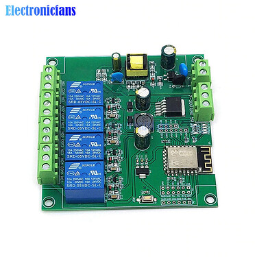
I have some esp12f relay boards that are great for esphome projects.
One project is my solar hot water controller. I’m using. 4 channel relay board for this to balance available gpio against relays.
I need to control:
- a pump,
- tank power,
- and a relay to swap off controlled load in certain situations.
so one spare relay.
I have minimum 3 thermocouples to track. A PT1000 in the solar array, and a NTC 10K B3950 in the top/bottom of tank. Theres some other ones that would be good to put in the system but those are the minimum.
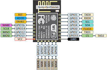
The esp12E only has one ADC pin. So what to do.
The ESPHome docs on thermocouples points out that you need to have a resistor inline and pull the value off the voltage divider to the ADC pin. So, in order to get more adc pins, I need a muxer. ESPHome already supports the MCP3008 which gives 8 channels on SPI. If we stick with the SPI stuff, theres the MCP23S17 which gives 16 extra digital gpio, which is useful on these gpio restricted boards. We could just throw some resistors on the board with some headers, but to make it more versatile i was thinking of using a set of MCP4261 digipots which theres some code already out there for. again, sticking with SPI. You dont want to run power through every sensor all the time, it can heat up the thermocouples and give bad readings. so you need to be able to swap them on and off. To do this something like a power gate array like L9825TR or MCZ33999EK to do low side switching.
So my thinking is provide 16 analog, 16 digital, 16 digipot and 16 low side switches. That makes a pretty powerful little expander board that can read thermocouples and other analog sensors (like gas sensors, current clamps etc) while doing general digital gpio and being able to drive small components like leds, solenoids etc. on the power gate array might even be able to do something fancy to support multiple supply voltages, since you might want leds at 5v and solenoids at 12v or something. Those power gate arrays can also support some interesting shared pwm functions, so you could drive a bunch of leds at a shared intensity or something.
I’m thinking of just throwing all of this stuff on a jlcpcb board and setting it up with a bunch of headers so it can be wired for each project with jumpers / solder bridges / dip switch arrays or something. I could potentially do something fancy with more gpio expanders to do ‘configurable wiring’ but its probably a bit much. at what point do you just plug in an fpga lol. Plus cost management is a thing, and the boards dont need to be dynamic at run time, just dynamic for each use case at build time.
I could do it all with I2C chips as well, i just started with and stuck with SPI. Might be worth refiguring the chips to save the 2 pins but was working for the parts that are already supported.
For those who actually know what they’re doing, whats the big fatal flaw here? I can see some obvious ones like ‘isnt it easier to have an esp32 dev board and a separate relay array?’. Kinda, kinda not. You still can run out of adc (or otherwise) pins fairly easily. still gotta wire up resistors and its nicer to have it on a board and just configure esphome yaml to get the right settings. Plus these little esp12e boards get nice bonuses like 240v ac or 5-30v dc input and switching, 3.3/5v regulation etc. They’re just great to integrate.


