Nog3's M365 Electric Scooter Upgrade Log

I recently purchased an M365 scooter to do the 13km trip in from home to work and from work to the space, and so far it’s working.

But there’s some things I’d like to do for improving the longevity of this machine and make my ride a little more comfortable and safe.

There’s a few things I’ve already done to improve it, including:

  • Adding Slime to the tubes to mostly handle punctures
  • Modifying the firmware to set a max speed of 25 km/h in eco mode, as well as tweaking the braking characteristiscs.
  • Adding foam inside the battery casing to protect it better from shocks.

Future improvements, in order of importance to me are as follows:

  • Adding a support for the back mudguard/fender
  • Adding reflective tape for more safety
  • Adding bike lights for safety
  • Adding an ignition key lock
  • Upgrading to 10 inch tyres.
  • Replacing the bottom battery cover with something more sturdy and countersinking the screws for this.
  • Widening the deck to accomodate my feet better, also adding grip tape.
  • Adding indicators, since it’s unsafe to take your hand off the handlebars on one of these scooters.
3 Likes

Regarding the lighting… I use a simple NE555 circuit on my bikes.

This can be used to drive a LED strip in a flashing mode to make a flashing tail light if desired. Not sure what voltage your system runs… I run a conventional 12V system and so can use motorcycle lights for indicators and brake lights. If it’s a higher voltage, then you could run two sets of lights in series or use a step-down DC-DC converter.

Cheers for the advice! It’s a 36v pack under the hood, but I’ll likely be looking to use premade 12v flashers as they’re already environmentally sealed.

So there’s been a bunch of upgrades I’ve done to this m365, I’ll run through them one by one. In the meantime, I’ve done over 700km on it with only one flat which was caused when I was swapping tyres around.

Adding Slime to the Tyres
One of the biggest complaints about the m365 is that it uses air tyres, which leads to grief when you get a flat tyre.

Most of the flats I’ve seen have been ‘snakebite’ or ‘pinch’ punctures from the tube slipping inside the tyre while it’s not inflated enough but there’s also a chance of direct punctures. At the time I was doing this some helpful person had been dumping tacks on the coronation drive bikeway (bicentennial) and I wanted to be able to better handle this situation.

Slime is one of several products that are largely similar, which are water soluble liquid latex and fibres that you inject into your tyres in the hope that when you get a puncture the air pressure of the leak will pack this slime into the hole long enough for you to get home where you can do a proper patch repair.

Most bottles of slime are targeted at cars/bicycles though, so the volume calculation will be way off for the 8.5" tyres of the m365. I did the maths and found I should be putting 30ml of slime into each tyre.

I recommend visiting your local chemist and getting a small syringe for this, as it’s by far the easiest way to reasonably accurately get this amount in, and the nozzles fit inside the schrader valve.

First up you will need deflate the tyre with your finger or a tool. Then use a valve core remover to remove the valve core, so there’s enough room to squeeze the slime inside. The slime bottle came with a plastic one that basically died after the first tyre so I recommend investing in a metal one, 99 bikes sell ones that look like this:
image

Then, with the valve at its highest point on the wheel and the rest of the wheel below it, squirt in the slime.

Throw the valve core back in, (you can clean up any spills with water), pump it back up and go for a few quick laps so the slime doesn’t settle in one spot on the tyre.

Camera Mount

After seeing a bunch of silly shenanigans going on in front of me, I decided to grab a cheap action cam to go on the front.

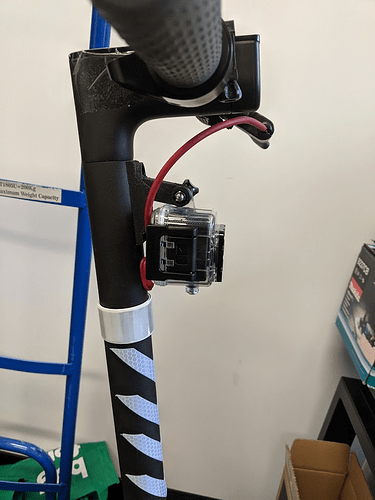
I tried a few different mounts

Take 1:


This was super flimsy and had a tendancy to ride up and down the handle, ruining the indexing of the footage.

Take 2:
This was actually a remix of one I found on thingiverse, ( https://www.thingiverse.com/thing:2764476) but I didn’t want to have to print and extender and was worried the extender would cause the camera to flop around too much. So I modded it in tinkercad and printed it.

Unfortunately it had a fatal flaw though as you can see in the photo, it tilted up and the handlebars on an m365 have a backwards rake which meant that the camera only saw the road like 2m away.

So, after some fiddling and a 15* angled part later, I got this which gives much more acceptable footage.:

Part is online at https://www.thingiverse.com/thing:3640494

1 Like

Quick update, the 3d printed mount is cool and all but unfortunately ABS seems to powder and get stress fractures from vibrations like that which happen on the frame. This meant that the handlebars on my steering shaft were coming loose as the print deteriorated… I don’t recommend using the print or using the handlebar mounting screws for accessories like this unless they’re solid. Also apply loctite.

This is what I’m now using, which I’ve dubbed the ‘crotch destroyer’.

Widening the Deck

So a few weeks back I measured up the existing deck, adjusted the outer edge to better fit my feet and then laser cut a template for how it looks.

Thanks to @crofty for the plexiglass this was made out of, it was a perfect fit:

@Mick_Morrison donated me some 16MM marine ply and with @ltp on a weekend in the workshop, I screwed down the template.

Cut the bulk of it with the bandsaw.

Then used @ltp’s trim router to follow the edge of the template using a follow bit. Before:


After:

Before finally using a rounded follow bit to round off the edges.

This is how it looks on the deck, as of right now.

I’ve got some M4 wood t-nuts to mount to the top before sealing it and adding grip to the top. I’ve also got an assortment of washers, bumpers and giant mudguard washers to hold it on. Stay tuned for that sometime in the next fortnight.

Adding Bike Lights

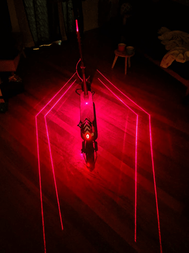
The first of my new lights arrived the other day, so I threw it on the frame and turned the lights off to see what the effect was. I guess it’s visible fairly well at night now.

2 Likes

Have you tried casting using a 3d print as the mould?
Might be worth looking into if you haven’t explored this possibility.

Indeed… but all too many drivers on the road do not understand what it means when the guide dog beside them barks 3 times.

1 Like

Rear Bearings Change
I have now swapped the original bearings in the rear for ABEC-7 rated ceramics and the ride is much smoother. These came from Plaig and were about $10 each, the rear hub uses 6001-RS style bearings.

I did this using the hydraulic press in the metalshop as well as some random bits of pipe and alu rod.


The jack


Pushing the bearings off the axle


New bearings installed, old in hand.

New Deck Mounting

So after giving the new deck several coats of external lacquer I tapped in some m4 wood t-nuts.

Lacquering:

I had intended to add some DKL brand rubberized grip tape to the deck but the lacquer actually added enough texture that it’s comfortable and grippy without tearing up my shoes - even in the wet.

I then collated my motley crew of mounting parts:

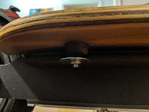
And made a stack of washers, bolt and rubber isolators such that the board sits on top of the rubber stopper and actually smooths out a lot of vibrations.

It’s now semi-permanently mounted and looks pretty swish if I do say so myself.

2 Likes

Brakes Upgrade

So another thing I’ve been working on to improve safety and maintainability of my scoot is to replace the existing calipers with a hydraulic cable-actuated caliper set from xtech. This has a few benefits, mostly around clamping power and better proportional control/non floating center but specifically it uses a common brake pad style that is super easy to source in any bike shop in AU. The existing m365 brake pads aren’t easy to source here and typically require ordering from china.

It looks like this:

I’d seen a bunch of spanish/brazilian youtubers using these on their m365 but there wasn’t much english documentation. The best I’d found so far was this video by Tommy Lepo - https://www.youtube.com/watch?v=xs4zpBWHW1Y

Now the existing mount holes on the m365 are significantly different to those, being 50mm apart and these calipers being 73mm apart. Additionally, the curve on the bottom half of the caliper doesn’t match up with those mounting holes.

This leads to some hacky but successful stuff like in Tommy’s video where he makes a bracket out of 3mm alu with this hole spacing:


Hole pattern

Installed bracket

This looked a bit janky to me and I didn’t want to stack washers and hope for the best. So I hung around a bunch in some non-english-speaking groups dedicated to m365 modding and saw a bunch of custom brackets being sold only in Brazil. I also found 3d printed versions which seemed like an even worse idea… so I asked if anyone could link me to that bracket or sell it to me.

A helpful person pointed me at this bracket, with PM-PM-F/R203 stamped on it.

I dutifully bought this, the calipers and a larger brake rotor which was recommended by a video on JR-Gadget’s channel - https://www.youtube.com/watch?v=XadDCJK8udU

It all arrived and I excitedly pulled off the old calipers and went to mount it all. Slight problem, the hole pattern on the bracket was still wrong. It matched the new calipers, but not the old mounting holes. Additionally the bracket was so tall that the brake caliper body was rubbing against the inside of my rear hub.

Dejected, I dug around and found this video by Alexander Kompmaister - https://www.youtube.com/watch?v=U7Q9N7KM8gE and discovered I would need to shave the mounting points down to 10mm and drill the new hole. The video didn’t go into how the second original mounting lug was done and as you can see there’s no clearance under the calipers to fit a full head bolt so I decided I’d use some m5 grub screws.

Fully Mounted:

Bracket Modifications required:

New Drill hole (23mm, based on Tommy’s diagram above):

Over the past fortnight whilst I’ve had time I cut off the extra height of the mounting lugs, cleaned that up and then using a belt sander carved out the extra clearance required to put the calipers up against the mount.

Last night I finally got around to drilling the second hole on the mill, using an m6 tap to index the initial hole in the mill and then pulling the tap out, moving the mill 23mm across and drilling the new hole and then tapping it.

Of course, I happened to brainfart and drilled and tapped it for m6 instead of m5. This is fine, but it does mean I now need to nip out for some m6 grub screws and drill out the original mounting hole to m6 as well.

Hopefully the next update will be with the new calipers on as shown in Alexander’s videos above.