Mount Ultra compact EQ
Payload (MAX) 7.7 lbs (3.5kg)
Mount weight 2.6 lbs (1.2kg) w/o battery
Body material Cast aluminum
Latitude adjustment range 0º ~ 70º
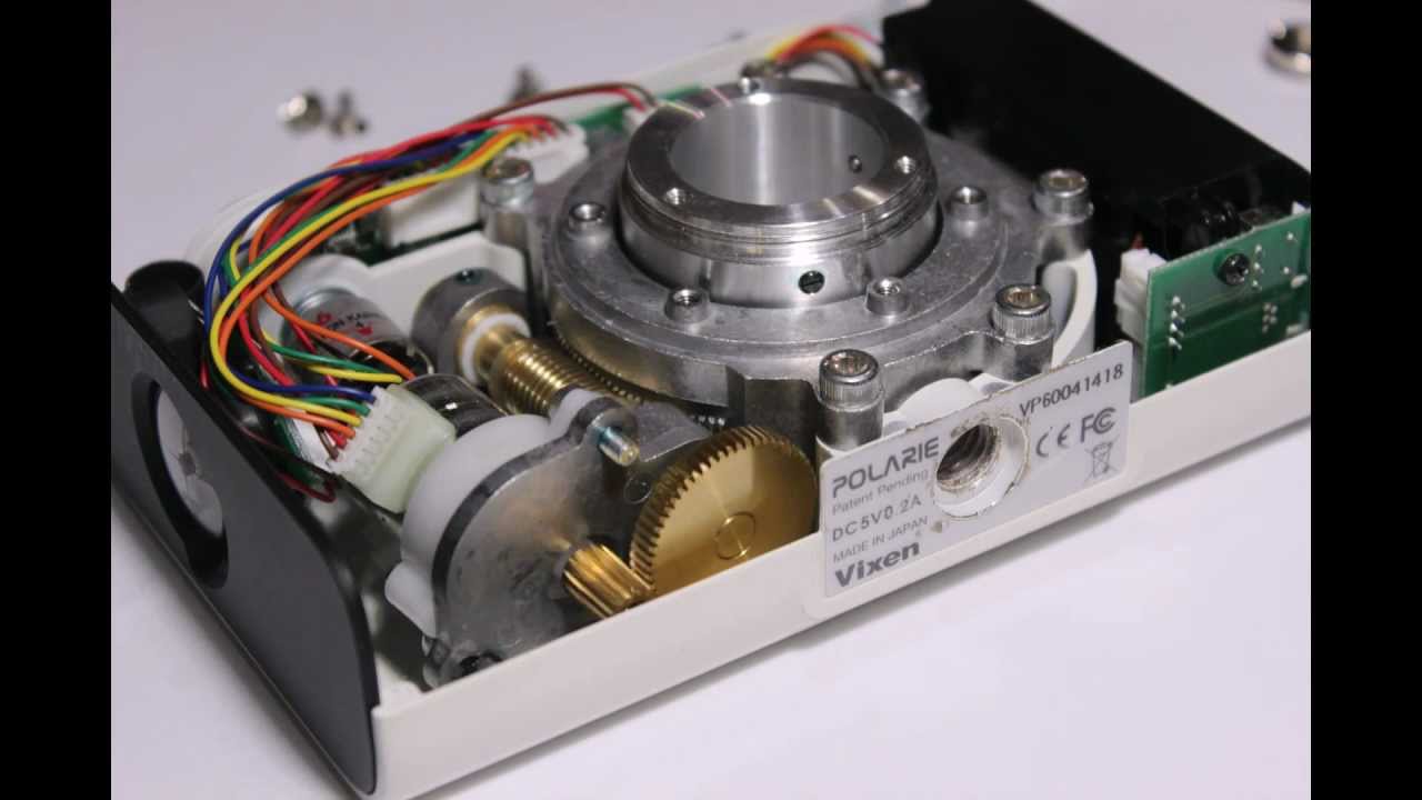
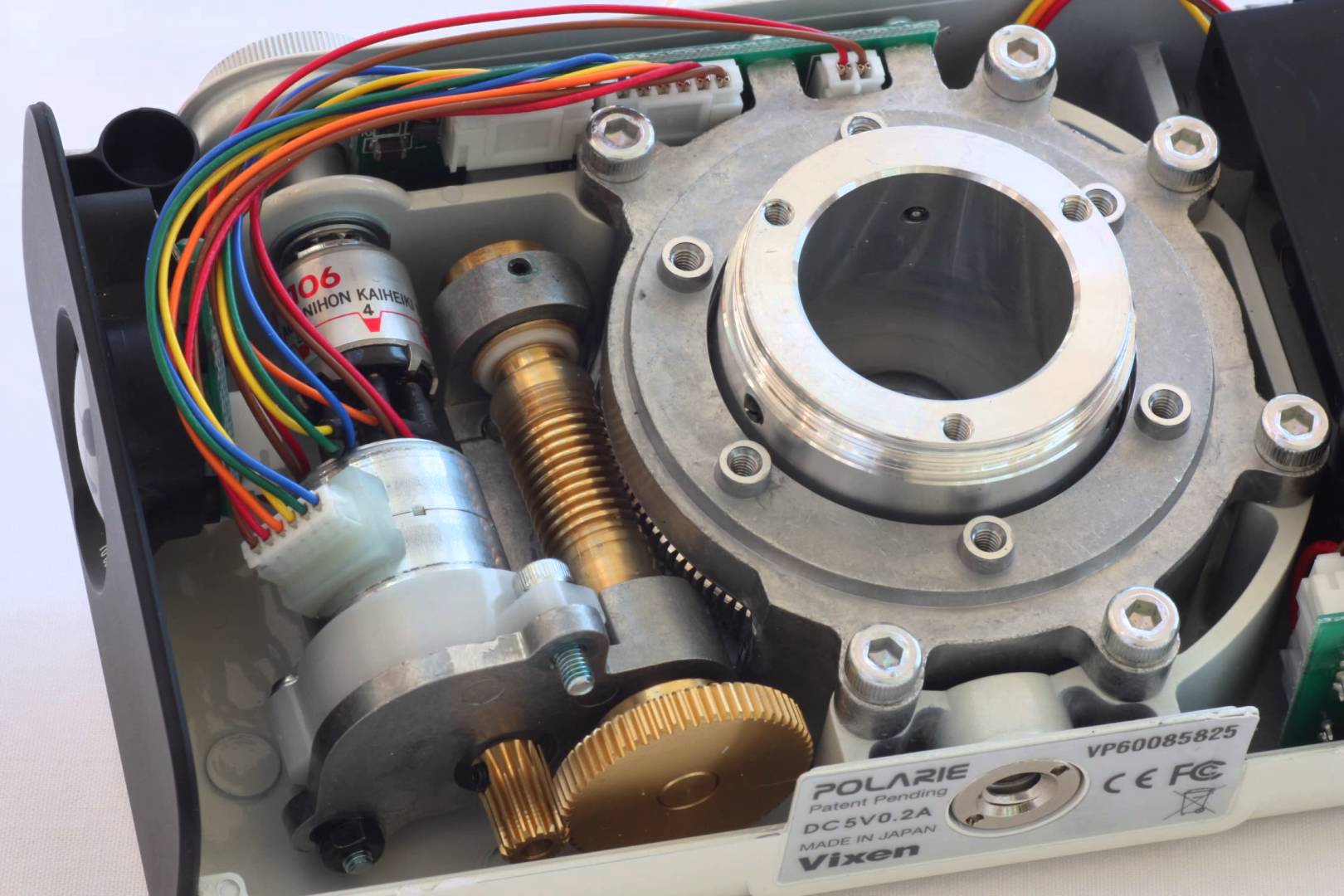
Worm wheel Φ80mm, 156 teeth aluminum alloy
Worm gear Φ11mm, brass
Bearing 4 pieces
Motor drive DC servo
Tracking R.A. automatic
Tracking speed 1X Cel, 1/2 Cel, N/S
Polar sight hole ~ 8.5º FOV
Polar scope 6º FOV with dark field illuminated (optional for #3303)
Power consumption DC 4.8 ~ 6V, 0.06A at Max load
Power requirement 4 AA batteries, or External DC 9 ~12V, 500mA
Duration of operation 24 hours at 20ºC
Built in accessory Latitude and azimuth adjustor, Compass
Dimensions 153 x 104 x 58 mm
Operation Temperature -10~40ºC
Base connect 3/8” threaded socket
Warranty One year limited
Important note:
The size of the main drive gear and bearings is directly related to the weight the tracker can take, and larger gears results in smoother operation and less periodic error.
Doing some study it seems 5mins is rather optimistic for even purchased consumer grade trackers. Perhaps a margin of error for 2 min exposures would be more reasonable.
I used this to figure out the relationship between the rod length and angle. So once the distance travelled per rod rotation is established (from specs or experiment), the number of steps per degree can be calculated, and therefore steps per second.
Based on this, even with a barn door design, a 200 step stepper motor should be sufficient. Microstepping is even better.
We only need to do about 1/4 degree per minute, which in the barn door design at 290mm is 1.26mm of rod per minute - quite doable. 30 mins is 37.9 mm. We can change the length from the hinge to the rod to make it smaller, and then our rotation is even smaller. (and I suppose, accuracy lower)
I have a bunch of photos of my notes which I’ll post later.
We should do a spreadsheet or something so we can tweak the parameters.
Anyway, control design is pretty easy -
Arduino or maybe even attiny
Stepper controller or high-current driver directly from arduino
two buttons - incline and decline, press to run, hold to move quickly in either direction. Probably not auto-rewind to start with, so we don’t burn out motor when it reaches bottom, ie attended. Otherwise we have to track steps moved.
All arduino really does is control step speed. For best results use a real oscillator ie not internal clock, or even external real-time clock. Probably fine for 5 mins though.
Independent of hardware/cog design - just change timing to suit.
But these notes are for you. I also covered the worm driven-cog thing you’re keen on like the above units for sale, but haven’t done it in the spreadsheet yet. I think that one would be a lot harder to build, as you need a sturdy custom-made cog with good bearings to hold the heavy camera at an angle. Which is why I favour the barn door tracker, at least as a first instance, yes. But if you can see how to do it, I’m keen to help with the control side - which is the same either way.
The point of this was to determine how much accuracy is needed, and a 200 step motor is fine even in the most basic case with a threaded rod.
Bear also said he had a 1:50 worm drive gearbox i can have with mounts. The considerable amount of torque from a worm drive shouldnt stress the motor. And he said the weight rests on the bearings and gearbox assembly, not the cog.
That’s pretty cool, though it eats significantly into your budget. It’s pretty similar to what I scribbled, though sturdier.
But it uses a DC motor, not a stepper, so I’m not sure how you maintain precision without feedback, under different loads (different orientations). Even still it should work ok for short exposures, or with calibration each time.
Do you know how to mount that onto a tripod and ball mount?
Its expensive but its an example of what is possible to obtain. There is a gear place in archerfield that i might ask about this stuff.
Also, working with my 2min exposure time minimum I worked with an engineer at HS to work out the mimimum amount of tracking needed for a 135mm lens (the zoomiest i have) to smoothly track without visible streaking and it came out to be a 1 rpm worm driving a 12 tooth gear.
Which means anything i use (im thinking a minimum gearing of 50) will be smooth enough to exceed my minimum spec. The rest is up to the motor control.
50-100 is buttery smooth, 250-1500 is grossly excessive.
Your calculations are the same result I got. Some of the info I looked at suggested that even in the worst case, moving the angle every 5 seconds (manually) would be sufficient. So that’s 12 movements per minute. Obviously we can achieve much better than this with computer control.
The number of teeth is irrelevant, unless you’re constrained to a particular motor speed, in your example 1 rpm. If you could get a geared DC motor that was guaranteed to have a constant RPM, and the right number of teeth (a factor of 1436), you wouldn’t even need steppers or control circuitry. I’m not sure about those motors on the worm gear site, they say “precision” but I don’t know how it can maintain speed in all circumstances - to the best of my knowledge DC motors don’t work like that. Otherwise, with control circuitry and enough resolution you can handle any number of teeth.
But I don’t get why you want to do this worm gear design when you started off doing a barn door, bought the stuff, and it’s been shown to work well for cheap? Honestly I just want to know if I’m missing something. Is it too big, or not sturdy, do you think it’s less accurate, or just not look the business? Is there a technical reason?
Less math.
Also, doesnt need to be reversed.
Worm drive is more compact too.
The items i bought for the barn door was 1 piece of 1/4in rod and a hinge, a total of $4.15.
The stepper and ballhead mount are project agnostic. And I havnt purchased them yet.
Also, at the time i bought the rod and hinge I was not aware of another method. My initial research looking up “star tracker astrophotography” in google yielded a lot of amateurs building barn-doors.
Digging a little deeper into professional manufactured products, none of them feature barn-door construction.
You’re kind of trading build complexity for maths. Maths can be done and redone on paper. And I’ve already done the maths.
The “professional” manufactured products are compact because that looks good to consumers and is easier to transport and market, etc. I’m sure they work fine though.
That scissor thing is basically a barn door with a different action. I thought it was too long and flimsy looking though.
But I appreciate that the worm drive design can be more sturdy, convenient and last longer.
So if you’re not using them, can I have your barn door bits and make one, and then we can compare them?
So on Tuesday we put together the simplest example of a barn-door tracker that we could in the time. Mostly from bits and pieces that were lying around. This prototype proved that the motor was able to rotate the threaded rod to raise and lower the top half, at different speeds.
It won’t be quite suitable as-is for the following reasons:
hinge has too much play, ideally would extend the whole edge of the platform
we couldn’t find a coupler for the motor shaft to the rod, especially since they are different widths. so we used a rubber hose attached with zip ties. The hose was not straight so the rod doesn’t turn entirely straight, which causes the top to wobble around, not helped by the hinge.
It was fairly easy to stop the motor by holding it, and at steps < 1ps, it sometimes stalled
the nut we were using was a bit rusted, making the last point worse.
we didn’t put the weight of the camera on to test
So we need:
a straight rigid coupler allowing differing shaft widths
smoother nut/leadscrew, and oil
better hinge (piano hinge?)
maybe a more powerful stepper - even if this one seemed to work, it is important not to miss steps
Also
the motor and rod don’t really pivot, so it will only have limited throw before catching - but as 5 minutes is only 1.25 degrees, we can probably achieve that.
Future:
thinner, lighter wood - determine how much space we need for the mount
nut and motor pivot mount (currently just loose screws) - pivoting Delrin nuts, and 3d printed or bought mounts.