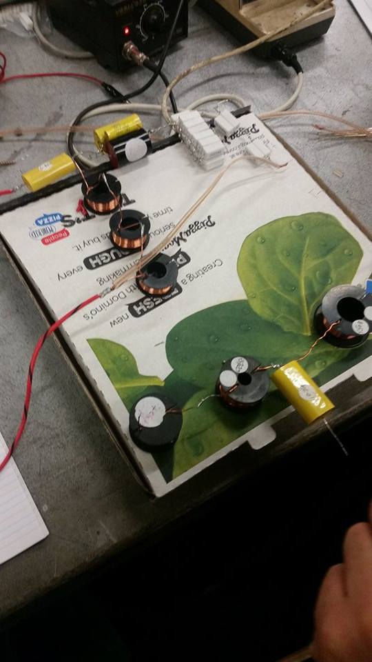
Project: Pizza Box Crossover

So last night @Svenska hit me up to make a crossover for the woofer/tweeter speaker box @rut4ger was making. I am happy to announce success, our Pizza Box Crossover split the audio signal in some capacity.

The next step is to refine the idea, and for that I need suggestions.

I aimed for a frequency split of 2.5k, which according to my maths is pretty close to what we want, but I will look at the charts and try to match it better.

I used a third order Butterworth system, and attenuated the tweeter down from 92dB to about 80dB, with the woofer sitting at 87.5dB.

I am researching this like a mad thing ATM, any thoughts and suggestions are very much appreciated, we all want to make this a totally kick-ass sound system.

My brother has an advanced diploma in sound engineering, and I’m dragging him along with me next Tuesday to have a look.

4 Likes

Awesome! Do you have any photos of your work so far? :slight_smile:

Sven does, he’s going to send them to me sometime and I’ll put them up on the blog.

So, I’ve stumbled across the idea of using an Active Crossover, the biggest problems would be that it would have to be boxed separately, as it splits the signal prior to amplification, and it would need two amps, one to drive the high pass, and the other to drive the low. Something like this would be pretty sweet.

Otherwise, on the passive front, I have been reading this very interesting article on designing the perfect passive, and while he goes pretty over the top, using his suggestions we may be able to come up with a decent down the middle approach.

1 Like

Oh, and as an aside, those yellow capacitors are Polypropylene if anyone cares. 10uF 400V PP Caps go for between $10-$20 a piece on Mouser, so if no kind person has done it by next Tuesday I might find them all a proper home, rather then sitting in boxes in the middle of the floor there, as they are best used for projects that require filtering/timing/frequency/oscillating/audio type stuff.

1 Like

How many are there, I have a use in mind?

The caps? A heap, 1’s, 4.7’s, 6.something’s, 10’s, 15’s.

1 Like

I’ve been working hard of figuring out Mk. II so I can hit it with a flying start next Tuesday. My plan so far is to use a 2nd order Sub-Bessel filter. The Q on the Sub-Bessel is 0.5, a close approximation to the Linkwitz-Riley alignment, and I can switch the tweeters phase 180 degrees to cancel out any phase issues. Using a 2nd order will remove some of the problems associated with a 1st order, mainly keeping a lot more of the unwanted frequencies out, without introducing too much complication. The higher the order you go, the more precise the requirements on your components. I’m also going to stick with 2.5Khz personally.

I want to try the Bessel filter, because the Butterworth has a 3dB peak at the crossover frequency, which would be nice to eliminate as much as possible.

I’m going to integrate a Zobel Network into the circuit, to match the impedance of the Tweeter and the Woofer, so my first port of call will be to measure the actual impedance, so I know what to base the math off of, rather than running off the spec sheet.

I’ll also better tune the Attenuation circuit, ideally I would like to consider using a trimmer so we can adjust the tweeter levels to taste.

I plan on matching the capacitors as best I can, then grabbing some of the over-spec inductors, and unwinding them until they match the exact spec that I need.

If I have the time this weekend, I’d like to have a PCB drawn up with gerber files, and maybe we can get a rough and ready PCB etched on the CNC’s at the 'Space, or maybe @merseyless would like to give a hand etching one instead.

These are my plans, but anyone else is more than welcome to try different configurations etc. I’m not an expert, and if someone else puts out something that is better then we run with that, I don’t mind if it’s my design or not, all I want is these speakers to be as bad-ass as we can get them.
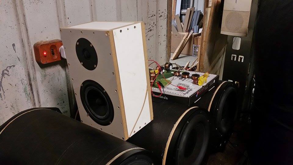
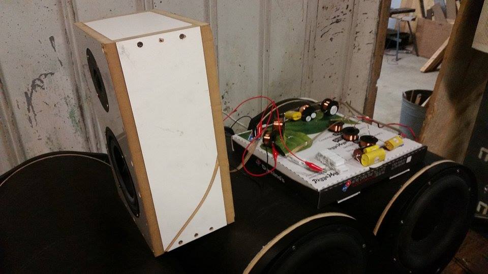
4 Likes

Damn, you don’t mess around.
I’m glad that I just dumped all that on you :wink:
Much better job then I would have ever been able to do!

I had a crack at a first order the other evening, Got literally nothing from it. There was zero difference in either of the output signals

Currently we don’t have a means of etching PCB’s at the space. I’m waiting for the lasercutter to get back up and running to test a laser ablation method of etching. That combined with an etchant solution may produce a quick and easy way of etching PCB’s. I’m yet to attempt using the CNC routers yet, haven’t gotten around to acquiring a V milling bit.

Sometimes looking at the speakers datasheet can provide you with useful crossover info. But this is normally only for the simple inductor/cap passive crossover. I have a 24bit DAC you could send some signals over for testing the crossover response if you’d like. Then again it sounds like what you are already doing is quite advanced so it might not be that useful. Good luck with crossover mk II

Can show you how to make up some etchant if you want.

Need a laser printer, iron or laminator, etchant.

All the materials are available at the space, including some blank PCB’s I’ve donated. Etchant is in the chem lab and the laminator is on the electronics bench.

The special paper required is not present, but I believe it is $15 for two A4 sheets at jaycar. If you print the design, cut out some of the special paper to the right size and stick it on top of the design with kapton on the edges before feeding it back through the printer again, it will work perfectly and waste the least amount of the special paper.
Though you might want to dedicate a printer to the task as there is a risk the tape peels off and gums up the printer, which is the last thing we need to happen to our nice photocopier.

Alternatively, I’ve been looking at the photoresist method, and to that effect have some photoresist film ready to be applied to blank PCB’s. It is a 2h process to make a PCB and needs a few extra chemicals, which is why I’m yet to do it. However, it does give excellent results.

Once the lasercutter is working, I have a spray I’m told is particularly effective for laser ablation. If this works, it means we have a 2 step process to applying a mask and with an etching chamber would make DIY pcb’s quick and easy. Very much a hands off process.

1 Like

Glossy photo paper works well for the toner transfer method.

If your design is simple, drawing it with a resit pen can work also.

Last option available at the space is to route it out
http://www.lpkf.com/applications/rapid-pcb-prototyping/design-articles/router-speeds-prototype-pcb-development.htm

I’ve tried glossy paper and couldn’t get it to work, though I only tried glossy photo paper. However, the back of that blue paper at jaycar peels off and covers up any tiny holes present in the laser printer toner, stopping pitting of the surface which is better for finer traces.

Glossy works good, used it down to the finest trace in eagle with minimal issues.

1 Like

I’ve used the laser printer + glossy paper + iron or laminator method too… and i personally tried both DSE brand (cheap) and Kodak brand(pricy) glossy papers and they both worked but the difference in ease was substantial … the $$$ brand worked way better.

Ended up working all weekend, so haven’t had a chance to do any more work on it.