The R2D2 Astromech project

Purchased this BRASA lamp from IKEA:

Marked out all of the holes to be cut and rough cut them with an angle grinder.

I had painted this but Didn’t like the quality or how it turned out I would have had to buy 2 of these to make one dome, having an inner and outer dome for attaching panels. I had tried 3D printing panels but were not happy with them. I also wanted servo actuated panels and the 3d printed ones were not going to work.

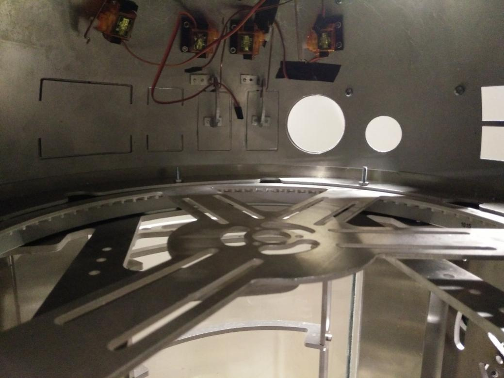
I was also able to control most of the panels using servos. I had fabricated my own hinges using my own design.

Logic displays: I used the 3D model from the club to create a toolpath for my CNC mill. Once rough cut, I used files to finish the pieces.


I used the TEECES PCB boards and soldered them up. I was a tight fit with the LEDs that I sed but it worked out in the end

They fit perfectly in the dome. I repeat this another time for the second from logic display and yet again for the rear logic display.

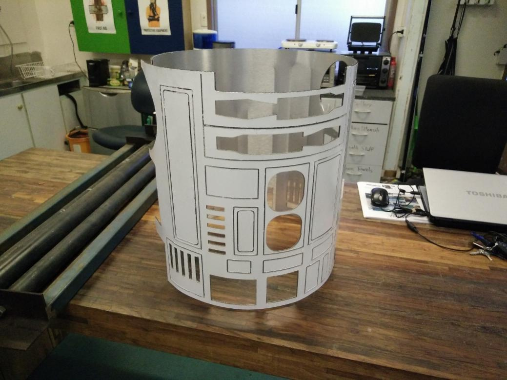
Moving on from the dome for a moment. I began work on the body. Using the CAD drawing of the skin, I used my CNC router to cut out the body skin. I know this is a bit out of order, but I was confident about this step.


I actually had to build a ring roller large enough to accommodate this, But by doing that I have a new tool for the machine shop. Once rolled the skin turned out beautifully.

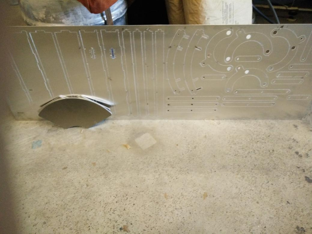
A huge thanks to Gary from Gary’s Droid factory for providing the plans for the body frame. I had a local person who does laser cutting and waterjetting laser cut my frame panels out of 3mm and 6mm aluminium.


Tapped all of the appropriate holes and the frame went together without much difficulty.


The assembly instructions for attaching the dome to the frame were quite lacking. Mostly because there were multiple different parts for different domes. I finally found a combination that worked.


Success.

Just for grins I put the skin into place. Almost looks like a droid.

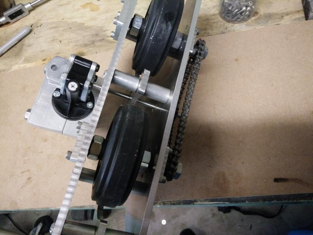
Moving on to the feet. I’ve decided to design the mecanice all myself. I went with a 3 layer 6mm aluminium frame. So more time on the CNC:


The wheels were taken from a rolling cart from Bunnings ( Home depot for you Yanks ) I’ve taken the swivels off


Like other designs, I went with the dual wheel chain drive. This is #25 chain

The motor is a 190RPM 12V 90 degree power seat motor. I’ve machined off the acme lead screw and attached the #25 chain sprockets.

1 Like

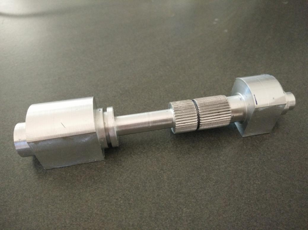
As I’m 3D printing the foot shells, I thought I would take a bit of a break. I decided to do something fun and machine one of the shoulder hydraulics

Shoulder hydraulics finished.

1 Like

So it has been a while but I’ve made progress on one leg. I did only one leg because if I made a design mistake then I only made it once.

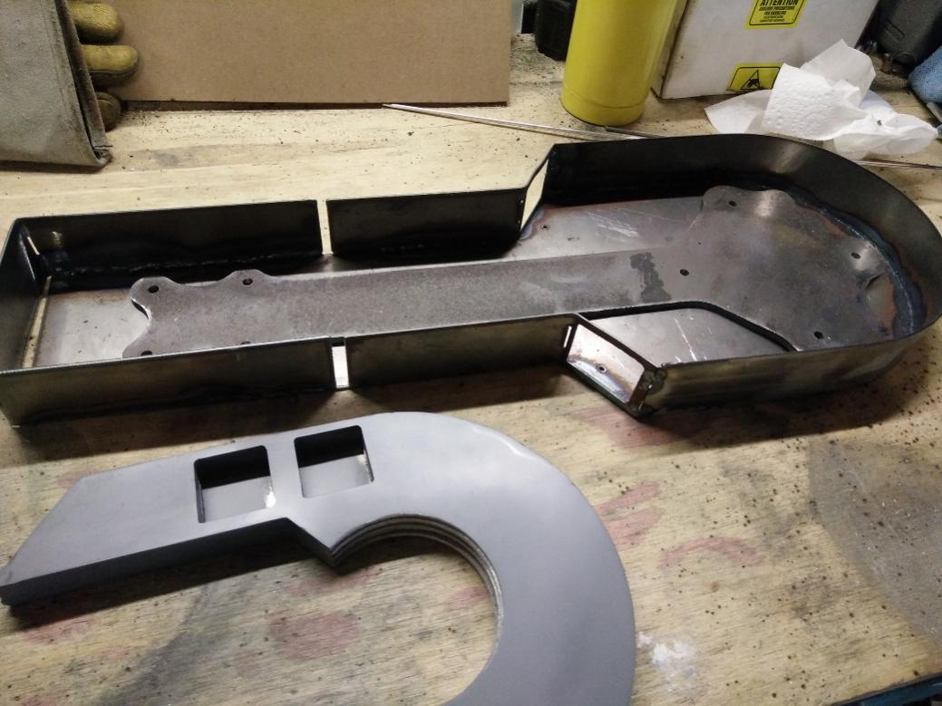
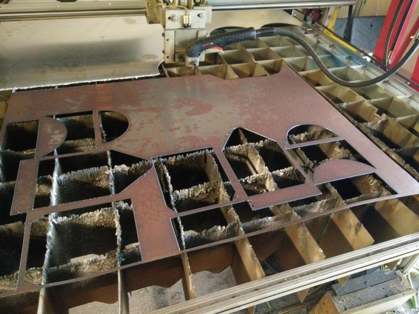
The first thing I did was cut the basic shell of the leg from 1.5mm steel on the CNC plasma table. This material by itself would not be strong enough to support R2’s weight, So I also cut what I call a “leg bone” from 6mm steel. Once all the parts were cut, I TIG welded the shell together.

For the horseshoe, I cut 7 individual pieces of 3mm aluminium and tig welded them all together. once together I machined the edges and used auto body filler to fill in any gaps or holes. Then the final piece was sanded and primed.

1 Like

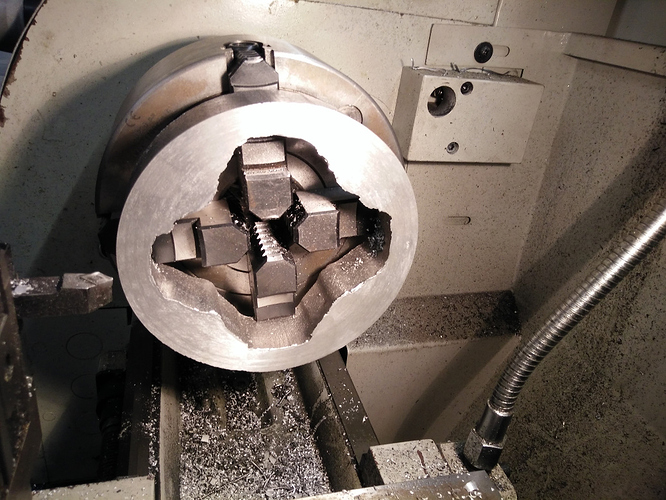
For the Shoulder hub ring (I didn’t really know what else it was called) I opted to use my foundry. the alloy was ingots from a car cylinder head. I first 3D printed the pattern to make the green-sand mold.

Once the alloy was poured, the rough casting came out with the risers and sprue attached. So those had to get cut off in the band saw.

Then chucked up the the 4 jaw on the lathe to clean up the surfaces.

Once machines to spec I located and drilled the 4 holes from the leg to the body frame.


And test fit.

I 3D printed up the booster cover and also sand-casted from aluminium. The quality wasn’t great, but body filler works wonders. I also installed the hydraulic and the buttons in the horseshoe and begun machining up the leg booster.

1 Like

I’ve machined up the inner shoulder hub. I didn’t get photos of the pieces but the hub is made from 6 individual machined parts.

2 Likes

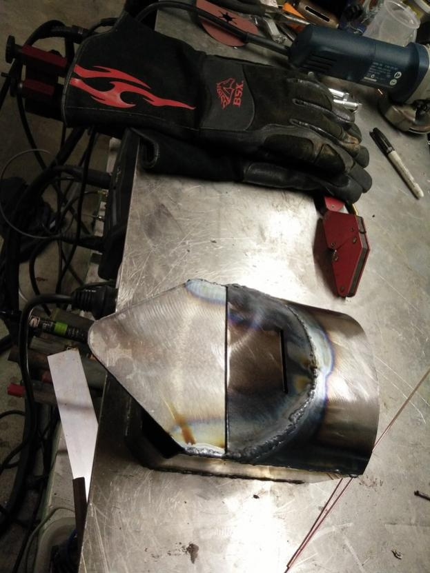
Built both ankles. I started out with a sheet of 1mm steel. On my plasma cutter I cut out the shapes:

With a sanding disk on an angle grinder I removed the rust:

Using my TIG I welded up all of the faces:

2 Likes

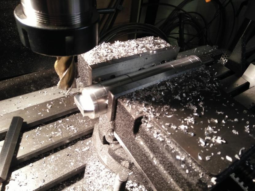
Turned up the ankle cylinder on the lathe. Here I am milling off the sides

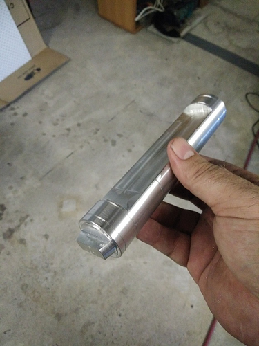
And done

The wedge was 3D printed. This is pre-painting

I have the deco piece that goes on the front/back of the ankle printed up and painted, But I didn’t have a photo yet.

1 Like

I’m really kicking myself for not taking more photos. But I’ve make some progress on the feet. Not in earlier posts You’ve seen me make the mechanical part of the feet. Now comes the hard part ( for me ), the cosmetic shell. I opted to go with a variation of the flat pack drawings here. It’s a variation because I needed to tweak the design slightly for the design of the innards. I managed to get one foot TIG welded up and just about finished and started on the second.

For the Battery box I cut a 76.2mm ( 3" ) aluminium pipe in half down the long axis. On my CNC plasma table I cut the sides and the endcaps. On the right of the photo you can see the welded up battery box before sanding. You may be able to make out the sanded version of the foot on the left. For the half-mood protrusions on the battery box I opted to 3D print them, bog them up with auto body filler and sand to blend them in with the alloy.

1 Like

I’ve painted and installed one of the feet. I had to cut out a section in both the foot and the battery box to accept the drive motor. You can also see that I’ve welded up the center foot but not done any innards or finishing on it yet.

3 Likes

As many of you know I’ve been working on finishing the feet. I’ve machined up some retainers for the braided cables

I’ve installed the braided cables into these slots. They are supposed to be a bronze coloured cable and I’ve tried electroplating one of the cables in copper to get a rusty color. What actually happened is that the cables turned purple. Not only that but the plating seems to just wipe off with little effort. This is due to improper plating. So for now I’m going to leave them shiny and revisit the aesthetics later.

Now fully installed.

1 Like