I’m going to build a jet engine using an automotive turbocharger! Something I’ve been wanting to piece together for a while now, I’ve started obtaining the parts to put this together.
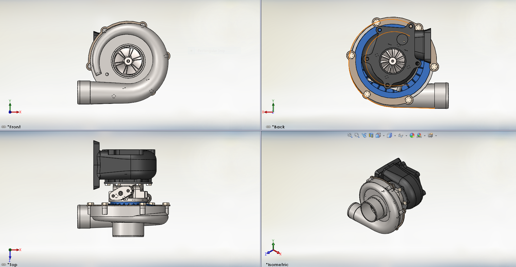
I’ve taken the first step and picked up a turbocharger second hand from ebay, it’s a TD03/04 model (I think), from a Nissan Patrol. No pictures yet, but here’s an awesome drawing someone made in Solidworks:
I’m going to try and plan out this build in Solidworks first, mostly so I can learn how to use Solidworks, but to also make the cutting/fabricating of any parts easier. It’ll be the first time I’ve ever planned something like this out.
To do:
Combustion Chamber
Flame Tube
Fuel System
Ignition System
Oil System
Parts needed:
Steel pipe to suit combustion chamber & flame tube
copper/silicon piping for fuel system
gas regulator for fuel system + needle valve for fine throttle control
spark plug + ignitor for ignition system
power steering pump + suitable motor for oil system
So the first step will be to start putting bits together in Solidworks using the maths provided from the above Colin Furze page. It’ll be a slow process but this post is a start!
The flame tube dimensions are calculated from the diameter of the turbocharger inlet, which is 63.50mm. The diameter is multiplied by two, the length is multiplied by six, so my flame tube needs to be 127mm in diameter and 381mm in length.
The combustion chamber is the same length as the flame tube and around 30mm larger in diameter. So I’m looking at 157mm in diameter and 381mm in length for the combustion chamber.
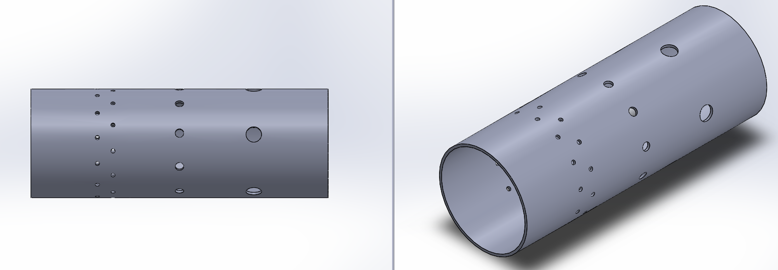
Delving deeper into the flame tube, it needs some carefully calculated holes in it so everything runs smoothly. There’s three sets of holes to go into the flame tube and they’re each worked out using the total area of the turbocharger intake. The first set uses lots of smaller holes and is 30% of the intake area, the second set uses fewer slightly bigger holes and is 20% of the intake area, and the third set uses fewer again large holes at 50% of the intake area.
My maths is terrible. But here goes…
Turbo intake diameter is 63.50mm, radius of 31.75mm
Area of the turbo intake (pi x radius squared) = 3166.92mm
Total area of primary flame tube holes (20% of intake area) = 633.384mm
Number and size of primary flame tube holes = 26 x 5.5mm holes = 617.76mm
Total area of secondary flame tube holes (30% of intake area) = 950.076mm
Number and size of secondary flame tube holes (30% of intake area) = 10 x 11mm = 950.3mm
Total number of teritary flame tube holes (50% of intake area) = 1583.46mm
Number and size of teritary flame tube holes = 5 x 20mm holes = 1570.8mm
Total area of flame tube holes = 3138.86mm
Turbo intake area = 3166.92mm
Difference = 28.06mm
Looks about right, yeah? I essentially guesstimated the number of holes for each stage, happy to accept any input on them! Now to fire up solidworks…
And I’ve already spotted a mistake in my calculations. The sizing is supposed to be 30%, 20%, 50% for primary, secondary, teritary respectively. I’ve done 20%, 30%, 50%. Should be easy enough to fix. I’ll sort it out after work tonight.
Thanks for the prod The project is still a go, I’m just being slow at getting stuff together. So I’ve got the flame tube designed and have cut a length of pipe ready to be drilled and I’ve also cut and formed the flame tube to turbine housing inlet adapter which just needs to be welded up.
On my to-do list:
Find a bit of pipe suitable for the combustion chamber, 150mm-ish. I spotted the bit of gal pipe out in the metal pile and it may be suitable, but i’d like some thicker walled stuff, plus welding gal is a no-no.
Get some flanges, to suit the combustion chamber and all the flanges for the turbo (turbine housing intake/outlet, oil fittings, etc).
Build it some more! Welding, lots of welding, I’d like to use the big mig for this because it’s neater (so much spatter from the flux-core mig), but it’s set up for aluminium at the moment so I’d need to wait.
Design some more. I still have the oil cooling setup to design, the gas injector setup, the igitnion setup. Design all the things!
Unfortunately health issues have cropped up again, and while it means that I’m not working so I have heaps of free time, it also means that for 5 days in every fortnight i’m 100% wiped out. But i’m determined to get this finished…one day!
In the interim, I’ve decided to see if I can hack together a pulse jet. I’m about 80% complete
re: combustion chamber:
from what I understand of the combustion chamber and flame tube, they don’t take the sorts of strain that need them to be “thick walled” like the turbo itself does … they just need to resist very high temperature/s. I’ve seen a combustion chamber made out of a toilet brush holder from ikea! ( less an 0.5mm stainless, possibly 0.3 mm ) any old bit of roughly 1mm+ stainless (or 2mm+ mild steel ) should work here.
The turbo in made by the car company as incredibly thick walled / strong because it’s got to contain a sharp spinny thing going at 100,000rpm or higher ( and these tend to disentegrate spectacularly if not constrained by their housing )
re: welding galvanised pipe, yes you can, it’s easy. just do one of the following:
1 - grind the gal 5mm or more away from the joint before welding, and get a nice standard weld.
( that’s the right way)
2 - weld “through” it - it will splatter a lot more as the zinc is vaporised, and these bits are more likely to get in your shirt pocket, or socks, or shoes, or head, and then burn thru and onto you ( so wear appropriate protectives for these areas especially) , and you need good ventiliation, and if your welder is small, turn it up to a higher power setting. Keep the arc going hot and strong, and move the welder a bit slower than usualm and it’ll be fine.
( that’s the way most welders, myself included, do it)
re “flanges” : so you just need some stiff flat mild stock of a suitable size that you can put some holes into to make flanges, an anglegrinder, and/or a plasma torch is great here.
Ahh you know you’re right, I think I’ve been of the mindset that the flame tube is 5mm walled so I’d like the rest of it to be 5mm walled, just to keep everything uniform. But screw it. I think I’ll size up that gal pipe and use it. As for the flanges, I’m just being lazy haha… it’s something like $12 for a 10mm mild steel laser cut flange for the exhaust housing inlet…
It’s unfortunate for me to consider…but would anyone be interested in taking this build over? I’ve gone as far as the above designs in solidworks and acquiring the turbocharger…just with my health failing at the moment I’m not sure I’ll be able to see this through to completion