In this little hack
**- 6 position switch to select Mode on Ardupilot
- Sceen to display mode
- Barometer altitude and temperature display
- List of hardware** at bottom of page
6 position switch
Check out this great how too for adding the 6 position switch. I couldn’t explain it better
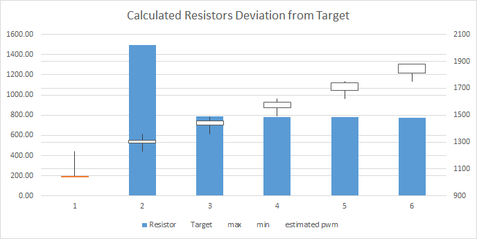
For resistor selection I found there was room for some optimisation.
I added a little excel sheet calc on git for optimum resistor selection for ardupilots expected ppm

Screen
OLED SCREEN
The OLED screen I used is i2c controlled which minimises wires. My previous hack used an old nokia screen which was not as wire efficient.

ARDUINO
The Arduino which drives the sceen is a Pro Mini Clone. But any ardunio you can fit in the case will do.
Head over to Git for the arduino sketch. - probably the easiest to download the whole git and unzip into your arduino sketch folder. If you already have a ‘library’ folder make sure you merge them. Alternatively the adventurous can unpack it manually.
BAROMETER
The barometer used to measure the pressure relative altitude and temperature is a BMP085. The BMP180 is the updated version of this chip and the same libraries will work with it  which is handy because it can be found a bit cheaper.
WIRING
The screen and barometer are 3.3V compliant but not 5v compliant. So be careful
Both the screen and barometer wire into the arduino’s i2c pins plus the power and ground.
To measure the 6 position switch, which runs at 5v, on your 3v arduino we will require a voltage divider. The middle of the divider (between the resistors) is where the arduino will sense the voltage on pin A0.
The code is commented to assist with alternate resister selection. Make sure you use resistors which are in the 100’s of kilo ohms added together. You don’t want to affect the radios ability to sense the switch. I used 150kohm and 3.3kohm but i suggest you choose your own and do the math 
To measure the battery another voltage divider is needed. This time we will use pin A1. Look at the commented code and do the math. I used a 3s Lipo so my high is 12.6V and low 9.3V.
Be sure not to fry your arduino by plugging 12v into it!
I managed to sandwich the boards together quite nicely. Held apart with headers wires and tape. held together with hopes and dreams.
POWERING UP
I used a little voltage regulator which I could select the voltage I wanted. Rather than trusting the on board ardunio, regulator I set it to 3.3V and wired it into the VCC pin. The power voltage divider can be wired to the input of the Voltage regulator to reduce wires everywhere.
After cutting out the turnigy badge i hot glued the screen in place then wrapped all the electronics in tape and poked it in. Ready to go fly 
**Happy Hacking,**
Hally
Next mod will be to use the arduino to read a gyro and send a pan signal down one of the channels for my gymbal camera. Stay tuned
Hardware
- 128x64 OLED screen - http://www.aliexpress.com/item/2014-Brand-New-1Pcs-128X64-OLED-LCD-LED-Display-Module-For-Arduino-0-96-I2C-IIC/1881133889.html
- BMP085 pressure sensor (or BMP180) - http://www.aliexpress.com/item/Free-Shipping-1PC-BMP180-Digital-Barometric-Pressure-Sensor-Board-Module-For-Arduino-Instead-of-BMP085/1763219907.html
- Arduino Pro mini clone - http://www.aliexpress.com/item/Free-Shipping-10pcs-lot-Pro-Mini-328-Mini-3-3V-8M-ATMEGA328-3-3V-8MHz-for/1911243495.html
- 6 position switch - http://www.ebay.com.au/itm/2P6T-Single-Deck-Rotary-Switch-Band-Selector-2Pole-6-Position-w-Knob-/301195072040?pt=LH_DefaultDomain_15&hash=item4620a01228
- handful of resistors and wire - http://www.calculatoredge.com/electronics/voltage%20divide.htm
- 3.3v DC regulator or DC variable voltage regulator - http://www.aliexpress.com/item/DC-DC-step-down-power-supply-module-3A-adjustable-step-down-module-super-LM2596-ultra-small/899939127.html


