The Tool Armoury

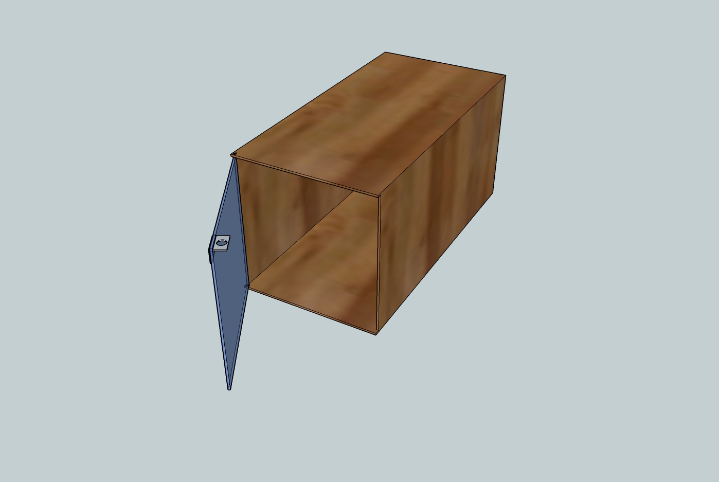
A terrible quick render of what a single box may look like

Overview

As part of the tools cause, I’m looking to build modular, chainable, lockable boxes. The goal is to have a touchscreen interface where a member can swipe in, unlock a box and take temporary ownership / responsibility for a tool (or toolbox, or anything restricted).

Current design is for a 2 part pcb (IGOR):

  1. Back of box, the bus passthrough. essentially 4 RJ11 ports in parallel for the RS485 comms.
  2. Internal near lock, door controller. Attiny85 board to listen to bus, microswitch, led, solenoid.

IGOR BOM

(Digikey part numbers and prices)

  • RJE0166001-ND $0.69 * 4
  • FDD7N25LZTMCT-ND $1.22
  • ATTINY84A-SSU-ND $1.63
  • 497-4285-1-ND $0.51
  • 1016-1171-5-ND $1.14
  • SMAJ12CABCT-ND $0.44
  • RGB LED - Unspecced $??
  • Microswitch - Unspecced $??

** Sub-Total ** $7.07

  • DC Stepdown (or these) converter will be used to drop to logic 5v from bus 12v

** Sub-Total** $9.57

  • Best deal on solenoids in bulk seems to be from Aliexpress. Shipping is the killer, single units are free via snail, but multiple units add cost quickly.

** Sub-Total ** $20.93

$20 for the locking mechanism is double our goal, but still within reasonable limits.

Suggestions for unspecced part numbers, cheaper parts etc are welcome.

Box Design

Box design is open for interpretation, so long as the external dimensions are divisible by 15cm, and the door locks with a solenoid.

Main controller / Interface

  • Cheap PendoPad Android tablet
  • LAMP/LEMP or similar stack for UI
  • Arduino + RFID as master RS485 controller

More Info

2 Likes

Some Microswitch ideas we’re playing with:

The criteria is looking like reasonably long throw or lever action and having it side mounted for mounting to the pcb. Suggestions welcome. Aiming to keep the part cost < $1.

My concern for this system of cubby holes is tool sub letting.

For example last Tuesday (11Feb14) I had the cordless drill basically all night for use in the chem lab. During that time I lent it to Sam once and to another hacker since them needed it and I was hogging it anyway. This was no problem for now, and even with he new system I’d have let Sam use it, however there is no way I’d lend it to another hacker who I don’t know if I’m solely accountable as via the new system. I’d be forced to either sign it back in, which would involve stopping what I was doing, packing up and cleaning the tool only for them to use it for less than 2mins.

Another unrelated note is the space has a massive box of green and red LED’s and simple switches that loki (I think, could be wrong) brought in. Both are attached to 2 wires about 100mm long and the switches form a circuit when held, rather than toggling on and off each time. I think you may be able to use 1 red 1 green LED rather than RGB LED’s you specced, thus saving some cost.

Anyway best of luck with this system, its sounding very good so far, and I look forwards to seeing a working prototype at the space some time in the future.

The answer is, if you dont feel comfortable lending the tool while you’re responsible for it… don’t.

We’re looking to make these repeatable and manufacturable, as in kits. Relying on availability of components like that would just make life hard when they’re not around. Especially when they’re the smallest cost percentage. Find me some cheap solenoids and we’ll talk :smile:

We are hoping to have a board designed by the end of the week maybe. We have a rough schematic at this stage and I think we’ve worked out the various design concerns.

If you want to help, the best avenue at the moment is to try and build tooling for helping people create boxes. I was looking at one stage to write a script that would produce laser/cnc routes for boxes of various sizes. It would be great to throw a 4mm plywood sheet into the big cnc sheet router and come out the other side with a box.

Hi Josh,

The issue with not lending that tool would have been that it would have stopped two people from doing what they wanted for the entire evening I had it, which is totally not cool. At present the only way round this issue for the cubby hole system is to have more tools than we need, but there will always be a bottleneck, regardless of what we buy. I’m still not sure what the solution is, and don’t really expect a reply with an answer, but I feel at least now its mentioned others can also have a crack at it, because its a shame to have such a basic flaw in the system, even if its absolutely in no way a critical one.

With regards to availability, I feel 2 basic LED’s will always be cheaper than a RGB LED, but absolutely air enough with regards to building a system that’s not based on what parts we happen to have at any given point in time. It definitely needs to be repeatable, not just for us either, it’d be cool if other hackerspaces could download use the basic design of this system, rather than requiring rare\odd parts or skills we just happen to have.

Sounds like progress is better than I thought! I’m going to try to get some prices and talk to people next Tuesday about either machining or lazer cutting (even heating and folding, which I’ve seen done) sheets of clear, vandalism resistant plastics, as from experience these can be great in there price to durability ratios. As a plus it does really do look good compared to simple ply, which is going to make it look a whole lot less like a hack and more store bought. Depending on cost it may even be economical to have the plastic lazer cut in house by the supplier, hence looking at getting quotes.

From memory price of 1220x2440mm (8xsmall cubby) 1/8th (3mm) thickness Tuffak (I think? its the hardened surface one anyway) Lexan is like $160 (edited, my old price was in NZ and way lower than here) which is about that of 12mm marine ply the same size from bunnings. Pricing is about linear with thickness for any of this stuff (eg 1/8th=50% 1/4 price), but the thicker you buy the bigger the discount for large orders. Of course bullet proof stuff is like 32mm thick and over $2.5k for 48x48" squares, as I found out when I asked last time I ordered the other, but that may be overkill for our needs.

Australian sheet traders sells the stuff in Brisbane, but i don’t know what thicknesses or price yet, nor will till I get round to phoning them, which may not be till Monday or so depending on if I get time tomorrow. They also do lazer or (massive) bandsaw cutting in house, but same deal regarding thickness and price for the lazer, I doubt the extra charge is much to cut it a few times with the band saw though, may even be free, not sure.

With the correct amount of funding, the Tools cause can easily sponsor having a second or even third cordless drill - negating the ‘lending’ problem.

The cubby system is one of a few ways to increase security at the space that was raised as a problem before we spend more money on Ryobi ONE stuff.

Just got a message back from these dudes, looks like they are willing to throw the mating connector in for us!

That is XH type 2 pin connector.
if you leave the message,we also can put some connectors,that can fit with this lock.

Very cool. I guess the question is are we confident enough in the design to buy enough parts for an initial run of 10+? I’m personally not financially solvent enough to do so, so it might require going to the group for funds.

Has the adafruit order gone through yet? i put an arduino on there for the project, I should probably add an rfid reader as well, unless you have one spare.

I have a spare Grove 125mhz rfid reader and cable for it, but I’m just
using it to debug the code for vendo’s RFID setup atm. I know we have some
stock of the newer version for use with the Snarc and Snarc+ boards we
bought.

Check out the read function here…

Ok here is my latest version of the schematic for the door controller board…
Can anyone spot any mistakes?

https://dl.dropboxusercontent.com/u/2391286/ToolDoorController.PDF

RGB Led? I think thats the only thing I can spot though.

There is a RGB led on the board at present (should draw a box around it to
show it’s one piece)
Though the diffrance between SMD and through hole on this part is $1.50
(SMD ~$0.50).
Having separate LEDS brings down the cost to ~$0.15 for through hole so
~$0.45 for three…

So the question becomes where and how will the LEDs be displayed?

I would assume they’d exist on the edge closest to the door so that their colour is visible through either the clear plastic or through a hole for the purpose. side mounted ones would be nice but standard should be sufficient. They dont need to be directly visible, but they should be able to give an indication of state from the front in a clear manner (green open, red error, off closed, blue please close door, that sort of thing).

So I guess the criteria is reasonably bright since they’ll be visible in the daylight.

Just a thought, but do we possibly want to try and put in support (but no components) to drive a strip of white/rgb’s as well/instead/on same pinout? That way we could light up entire boxes down the line, which might be nice for viewing contents and such.

Great idea Josh we could put the board on the underside of the top panel
and just have a surface mount led to illuminate box with some white led’s
all the time and use a rgb led to highlight box selected.

With the concern of lending the tools could the system have a forward
option in the return section.

Eg Option Returned in good condition
Returned in broken condition
Forwarded tool to [insert name here]

Luke I have a 24v solenoid in the mix that may be used as it is a lot
stronger than the 12v one I got for roughly the same price.

I have been unable to find a RS485 chip that would take 24V, thus at this stage it’s a 12V system only :frowning:

The rs485 chip selected 1016-1171-5-ND will only do 5.25v so I am not sure
what you are talking about :wink: with 12v only you will need to step it down
somehow or just use something like

AAAAAAAAANNNNDDDD… Here is the board layout… Coming in at 50x60mm in size!
Still need to change the switch and LED diode but there should be plenty of room in that area to do what we want…

Changed Schematic to include 2 optional drivers (Aux1, Aux2), either 12v LED strips or solenoids.
https://dl.dropboxusercontent.com/u/2391286/ToolDoorController_11.PDF

I note that Josh suggested 4x RS485 jacks in “parallel”…
RS485 should not use a star topology. it should be a multipoint bus with stubs kept as short as possible"

see this document “the practical limits of RS485” here: http://www.ti.com/lit/an/snla042a/snla042a.pdf page 5 ish.

The way that we are thinking of wiring the boxes is a comm line running down the back of the box.
This line is then split to the front of the box to the controller.
As such I don’t see this config being a ‘Star’ Network.
We will need to return the line to the next row below and zig zag the comm line back and forth to prevent the “Star” forming but this should be possible.

Josh: If we were to run the com cable at the front of the boxes instead of the back would that pose a problem?
If this is possible there will be no problem what so ever.

PS this is the RS485 chip that I’m thinking of using…