Could we just do it all on one pcb and have the board on the wall and the
sockets sticking out the back.
I was thinking that we could have a breakout for the 4 pins needed to control an rgb led strip, and using that would supersede the onboard one.
I’m sure theres a multitude of software based options. Lets concentrate on V1 for now.
Que? We have 4 lines on the bus, sda, scl, vin, gnd. I dont see why the comms lines cant be at 12v while vin is at 24 while the board uses buck converted 5v for logic? Not that it matters much until someone provides a source of solenoids better than the ones linked. Looks @denominator ![]() (nb, this will probably suck if we want to drive led strips as well. sticking to 12v sounds sane to me, I cant imagine that we will need oodles of pulling power.)
(nb, this will probably suck if we want to drive led strips as well. sticking to 12v sounds sane to me, I cant imagine that we will need oodles of pulling power.)
Looking good mate. I like the idea of aux outputs. Can we fiddle with this idea and the rgb led pinout to potentially drive rgb led strips?
Is it worth trying to do anything ‘smart’ like have the buck converter cover components in order to get size down? Would it be an idea at all to mount the buck converter upside down to prevent fiddling with the trimpot once set?
At the moment I’m envisioning these things either sitting on the right hand wall, in which case the micro should be at the right of the board, and then the led left of it; or sitting in dead center on the roof, in which case led in center, micro to the right/left, led strip breakout on the back and solenoid connector on the right. Thoughts?
Where is the rgb led on this board, I’m not 100% able to spot it?
It’s not a star unless someone wires it that way, its pretty clearly a multipoint bus. 2 ports to continue the bus, 2 ports to break out into children.
I’m not 100% sure how we could do that and have it not look terrible. the alternative is having 2 ports on the board, but that means running 2 cables into each box from the back, urgh. That also hobbles us a touch when it gets a little trickier to route all the boards when the box topology becomes non standard box-in-a-row. Its not impossible, someone just has to sell me on the benefits is all.
Well, the design requirements for the board are for it to be at the front near the door for the led and microswitch and solenoid. We were going to have all the brains on the back as part of the bus board and have a smaller dumb board near the door, but then realised that was silly when we counted the pins we’d need to break out over cable. So I’m not sure how we’d stick ports out the back and still be up the front to control/indicate everything.
From the front left of the board we have the Switch (Rather Large and needing to figure what typeof switch is needed here), then the RGB LED labelled ad D2 through hole (also needs changing to a better solution) then skip the next component to the door connector which powers the solenoid.
Up the left side we have the AUX connectors (AUX1, AUX2) and the cable for data’s at the back.
I need a 12V line to pull the comms line to 12V… Or do I?.. Umm let me think more on this one
There is one pin left that could potently drive RGB LEDs like this.
At present this is already broken out on the programming header (sck), should I also break it out elsewhere?
Umm, this could be a possibility for the RGB LED 
Thoughts?
I think it really comes down to “Is there space to put the code” on the micro.
ehhhh addressable strips is totally overkill. I was just thinking the 4 line stuff I buy from ebay on the cheap that you can snip up and solder. So long as the driving circuitry supports it, can we not just put it off the same pins as the onboard one?
45c per led is ok I guess. Nothing better on digikey? thats really the only stand out attractive bit.
Code shouldnt be an issue, its just controlling pwm on 3 channels, libraries just make nice interfaces.
presuming you have at least 3 spare IO pins on the microcontroller would it be worth putting a NRF24L01+ on each unit ( cost is a measly $3.40 for a pair, less than $2 per unit) to get rid of all the RS485 hassles and RJ45 sockets, and physical wiring, and etcetc…? )
Are you suggesting we run each box from a battery?
Though your suggestion is valid, I feel there is not much extra effort running cable for power vs running power and data in the same cable.
As long as we keep the diversions from the back of the data loom to the front under 0.5m in length and at low data rate we shouldn’t run into many problems at all.
Using this method we can achieve around 200 slaves on the same bus.
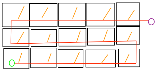
Please note, this is how I plan to wire the boxes (excuse my dodgy drawing).
Looking at the back you can see the main data loom shown in red.
If you want to add another row it should be fairly painless to unplug a section and patch a box in the line. The orange tap off the main line and feed the electronics at the front of each box. The Master node can be either the purple or green circles, the other is a termination point to stop data reflections down the line.
Remember the old coax networking before cat5?
Thats basically the same type of restriction that will be imposed here.
Wireless would be lurvely, but we still have to deliver power so it kind of negates the nicety of wireless. Running a bus like luke described should be more than adequate. It will probably look a touch hairier in implementation when we see the box stacking but no big deal.
On the other hand, wireless means you don’t have to run power through all
the boxes on the same cable. So you could have a set on one side of the
room, and the other, on independent power.
Thats a fair point. I guess at that stage my concerns would be:
- Increased cost per board, since we will still need connectors for power
- Reliable supply of the cheap wireless board (ebay is not reliable)
Trying to make these boards cheap as possible is a primary design concern.
Another concern I have is…
- How do the wireless modules talk to each other?
- How many nodes can you get per network
- Will there be any interference from
a) outside world
b) tools stored inside (metal tools blocking signal) - Do we need to code the wireless protocol
Basically, how robust is a wireless solution vs a wired one…
I’m currently messing with the nRF modules Buzz mentioned. There are nice arduino libraries and some of them at least should run on attiny, so you could get the price down.
I haven’t actually gotten them talking to eachother yet. I might have one broken one, good thing I have spares.
They are cheap and plentiful and not going away any time soon.
They appear to use a “pipe” way of communicating, not clear yet if this is for many devices, like a bus. Nor do you need to assign an address to the radio itself, it’s configured by the arduino.
As for interference, this would need to be tested in the environment.
Also, the Leonardo is really annoying to work with.
If anyone is still concerned about the RGB LEDs, I have 1000 WS2812B’s that I could sell to the space for 15c a pop.
These are the same that are used in the adafruit RGB LEDs and RGB LED strips.
Are they surface mount or on a led strip?
We’ve decided that V1 of the boards luke and I are producing (mainly luke atm, lets be fair with credit, heh) that we are sticking to wired for now.
Having said that, if anyone else wants to make wireless nodes or modules or addons to our system, its entirely possible, and we wont discourage it in the slightest.
I’ve just found these. http://www.aliexpress.com/item/Free-shipping-Central-door-locking-actuator-2-wire-actuator-12V-for-Central-locking-system-High-class/929905736.html
Thats half the price of the solenoids but not anywhere near as straightforward to implement in the build. What are peoples thoughts?
My thoughts …
They are an excellent idea and an awesome find.
Basically they are a 12v motor that moves a pin in and out it is
controlled totally different to a sol. Power is supplied to turn the motor
in one direction to open and the other direction to lock. The parts count
will go up on the board as you will need an extra 3 mosfet’s, Resistors and
diodes. You will also use another output pin (no problem at all)
They are bigger, stronger and more tamper resistant than sol.
It will use up more space in the box and I think they will not look as nice
slapped onto the side of the box.
After chatting with you about it last night about the design and my concern
of how easy it would be to tamper with the sol to unlock. I have come up
with another cunning plan to make it more secure with not much more work 
I plan on 3d printing a custom strike plate and casting it an aluminium
from cans. So the casting guys get ready because I have a project for you
to replicate many times.
Anybody have any sprung hinges they like and are cheap ?
@lhovo Thoughts?
Yeah, thats a certain concern. I think if they’re mounted to the roof and actuate to the side, you can just put a bit of plate in front to hide sins. they’re long but relatively thin by the looks.
I look forward to seeing it ![]() If you want to produce in bulk, you’d be best off making a mould to cast wax into.
If you want to produce in bulk, you’d be best off making a mould to cast wax into.
I see the complexity with these actuators being the same as a Servo
- how do I know when the door is closed
- for how long did we run the motor for
- did we lock the door or just locked the door open
Please correct me if I’m wrong, the next thing would be downgrading the extra outputs we have placed on the board to enable the extra circuitry to be driven. That said it could come out cheeper as we are driving a motor now. (need to do some research on this)
Unsure what the issue is?
Yes like every door (unless you deadlock it) you can get some wire and open it up, most people put some flushing down the join to fix this problem.
So my thoughts are yes, possible but could become unreliable..
There is nothing simpler than pushing a door close and it latching like all the other doors in existence.
Yep, its a $5 difference (which is 25% of per unit cost though) to make a system that, in one area, not going to be as reliable (door closing), and that cost saving might be eaten up by the extra component cost? If we have to lose our 3 aux outputs I wouldn’t be super duper happy tbh.