Just a though, but a book case like these.
Would that be a easy solution to making the boxes?
I can see us putting a door on, electronics and then a back and we have a tool system without to much fuss…
Yeah, It’s been suggested. My only concern is that its pretty wasteful space wise, and quite expensive. ie, a $90 shelving unit probably runs 150-200 by the time you hinge and door it, and it only stores, what, 8 power tools, in quite a large space.
Jimmy has suggested a 6mm board that he buys sheets for about $4. 6mm turns into 12mm when joined with other boxes, so it looks like it should be fairly strong in formation, and it allows builds to the size of the tools. ie 15x30cm for one drill.
In the end I’m agnostic though, whomever wishes to build boxes can build them however they want. I’ve just specced the 15cm rule as a way of making sure these things can all ‘mate’ together properly. I’m just commenting on cost efficiency.
I have been testing the attiny84 trying to get reliable tx, rx traffic.
tx traffic is no problem and all is happy, rx not so much…
At present I’m using the software serial serial library in arduino land sending and receiving on pins 9, 10.
After searching the internet I found this a tiny internal crystal tuner, but as you can guess it’s not working reliably enough for the program to find the right frequency.
So I’m thinking we may need a external crystal (which we don’t have enough pins for at present so dropping functionality will be required) or spend a extra $1 per board for a more powerful processor with hardware serial built in.
Thoughts everyone?
bigger processor seems the more logical move.
What is the cost of an external crystal?
What is the cost of going up a board to get more pins?
What are we communicating with over serial? the RS483 chip?
Around the $0.50 mark
Then next processor up is Atmega168 at a extra $1.20 over the Attiny84, the new chip will have hardware serial thus being more reliable than the software version.
There is also slightly cheeper version of the chip - Atmega88 at 88c more than the Attiny.
Difference being 16kb programming space vs 8kb programming space..
Both have the same footprint and pinout so can be swapped if you want something more or less than the one we get now.
Yes we need the chip to respond to commands from the bus, having a flakey RX isn’t going to help us in reliability. In the testing I preformed on a breadboard I was able to receive the correct character every 3rd-4th try so receiving a word would be bordering on impossible..
Hmmm. That sounds pretty clear to me. Lets go up to the chip that can do the serial reliably. That might give us some more wiggle room on features too I guess.
Good Catch on that one Luke. What are we up to on a per board cost now? $10-12?
I have enough PWM pins now for both the onboard LED and all AUX outputs now 
Basically this allows nice things like dimming and full RGB mixing to any colour.
Current schematic is looking like this
https://dl.dropboxusercontent.com/u/2391286/ToolDoorController_13.PDF
I think I might add a crystal as a option because I can now though it should be totally unnecessary.
Sounds fantastic.
I’m still keen to see pads for extra parts to drive things like those car door motor locks.
Sounds like we’re super close!
Oh yea.. Forgot about that well we have the pins for it now ![]()
Will look into whats required and how much space it’s going to take up.
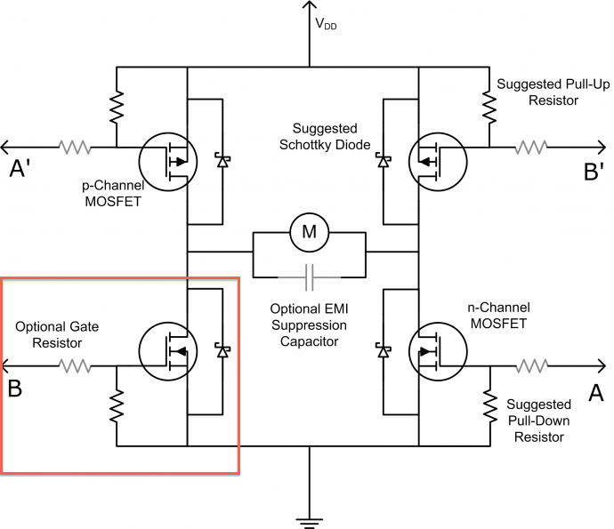
Ok, this is what I am going to have to build to add this functionality.
I have placed a red box around the section that is “Pre-existing” on the current outputs.
So how important is it that I construct this in the present version?
At a estimate it’s going to be a extra $4-5 in parts per output…
I would leave it off and on the boxes where you are going to use the “door
lock motors” use something like
thishttp://www.miniinthebox.com/l9110-dual-channel-h-bridge-motor-driver-module-for-arduino_p903443.html?currency=AUD&litb_from=paid_adwords_shopping&pla_adwid=9286587055_138818343_11036880423_67565068263&gclid=CPy7iP-Cmb0CFUUHvAod7i8Ang
or
build something similar or don’t populate those components on the board if
they are not required. How much dose the extra pcb space cost ?
Thanks denominator, you made me look a bit closer and I found this beauty → LV8548MC-AH
$1.75 easy to solder and not much supporting components needed, I think it’s a winner!
The next question is, will 1A at 12V be enough to power the motor?
It’s reasonably cheep, but I might be able to add this footprint on without expanding it much.
The biggest hassle space wise would be connector space.
Shall I try to add this footprint to the PCB?
Edit: I will need to increase the board size, there is no way I’m going to fit anything more on the present board. I’m finding it hard to fit a crystal footprint to the current size board. So do we want this option on the board? It will add 2 motor outputs and use most of the remaining spare pins..
Can any of this be added to the back side? What is on the back side at the moment, I havent seen any images.
As for motor driving chips/cost, I’d like to have the pads but lets not worry about parts for now. The extra chip cost should be managed by the cheaper cost of the motors, if we go down that path.
It’s not so much the chip space but the connector space that i’m worried about. Need a 4pin strip like the AUX outputs but single row only.
The logical place would be to place it to the right of the buck converter, but I have a component on the bottom layer at present with little to no wiggle room to move it.
At present the board is looking like this… Note the bottom side (blue) is “flipped” for easy viewing
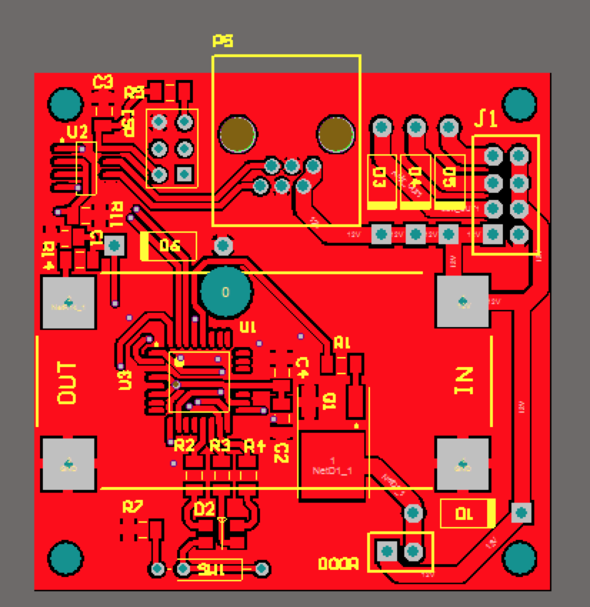
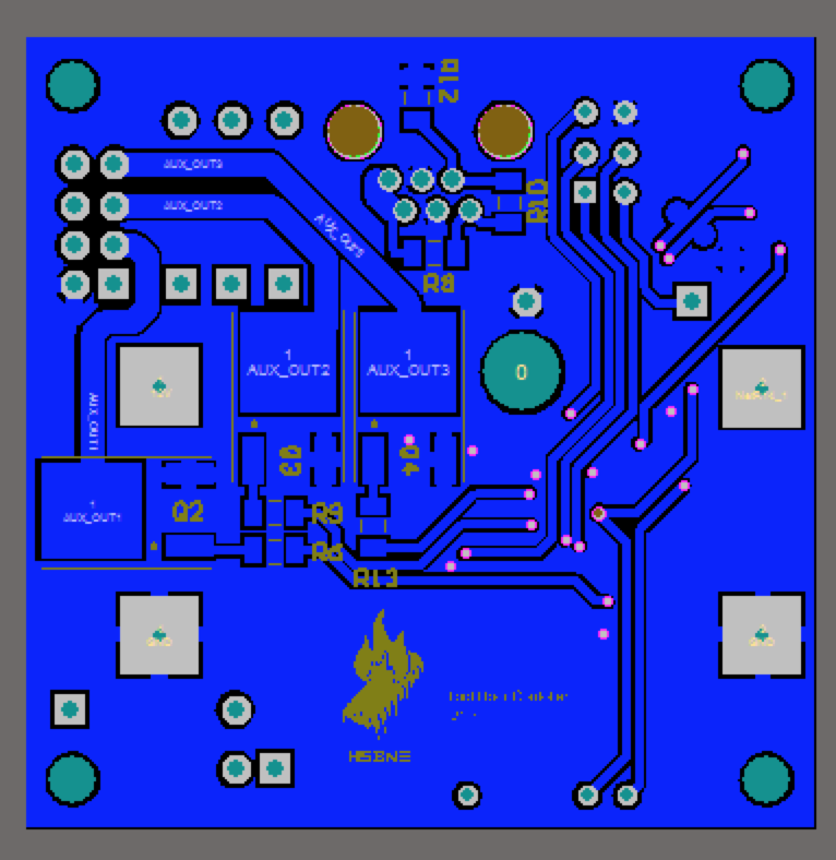
Could you move the items to the left of the door pins on the top layer more left and hence have room between them and the door pins? Also looks like theres potential to rotate the door pins to be vertical if needed. That should give you the connector space.
This is hopefully the final design…
Last checks anyone?
Are you meaning to drive Green led with MOSI ?
It was a handy PWM pin and is only used when programing the chip. So I’m
99% sure this should be fine…
There is 6 PWM pins on the chip, I’m using 3 on the LED and the other 3 on
the AUX outputs. So that’s why I’m repurposing the MOSI pin.
PS thanks for checking…
And here’s the breakout board, might as well place them in the same order and save on shipping…