VK4MSL/BM refurbishment

So, many years ago, late 2010 to be exact, I got the crazy idea to put a HF radio station on a bicycle. This has been a project that has been going many years now.

Early experiments were with a Yaesu FT-897D, a 9Ah SLA battery and a 6’ 27MHz whip from Jaycar. This worked, but was clumsy, and the battery didn’t have much puff. I revised the set-up to use a 40Ah LiFePO₄ pack (4 40Ah Thundersky prismatic cells in series) which helped with the battery life, but still everything was loose in an open basket, so no good in wet weather and definitely not secure.

I replaced the 897D with a Yaesu FT-857D and eventually moved to 10Ah LiFePO₄ packs (Lifebatt) which made things more manageable. The station everyone sees today (VK4MSL/BM Mk3) is basically from about mid-2012 when I bought my current mountain bike. The biggest difference here is I’ve now got 20Ah batteries.

It’s been a while since I’ve done HF bicycle mobile properly. Bicycle Queensland has approached Brisbane WICEN to assist in this year’s Yarraman to Wulkuraka bike ride.

WICEN generally use 2m and 70cm, and 70cm was a sticking point for me in the past, and so after a quick experiment with @vk4mdl’s Maldol dual-band whip, decided to bite the bullet and buy a couple of new antennas. I wound up buying a MyDEL VH-6 for the HF side, and a Diamond NR-7900 for the VHF/UHF side. (Both were purchased through Andrews Communications in Sydney.)

Last Thursday they turned up, and we got to fitting those. @vk4mdl made up an angle bracket for the new VHF/UHF antenna while I soldered new coax and sockets up. I spent some time Saturday tuning everything up. The new antennas performed well.

Sunday we did a rekkie run from Benarkin through to Linville then on to Moore. The station performed well on the trail when everything behaved itself. Good contact was maintained on both 2m with 30W FM and on 10m using 100W SSB. That said, it wasn’t all smooth sailing:

  1. The earpiece connection to the head unit has broken. (Knew about this weeks ago, just haven’t gotten around to fixing it.) I’ll need to take the head unit apart and re-solder that again. Maybe use some better quality wire.
  2. The left-hand control panel started to rattle loose. This was found (whilst inspecting it at Linville) to be the plastic on the rear of the box giving way.
  3. Part way between Benarkin and Linville, a fault developed on the control panel on the handlebars, causing a short on the “down” button. The “right” button wire also broke loose. During the run into Linville, this caused all buttons on the head unit to “lock up”. PTT still worked, but I could only turn the radio on/off, couldn’t change frequencies or anything. I worked around this at Linville by snipping the wire to the errant “down” button and doing without it.
  4. Nearing Moore, the VHF/UHF antenna mount fell off the right-side bracket. This is possibly a symptom of the bracket metal being too thick: it was a scrap piece we found around the hackerspace, and we had to sand it a bit to thin it out a bit.

Fixing (1) is easy, just tedious, and I just worked around the problem using the extension speaker I built before, but it’d be nice to hear stations through the headset in my helmet.

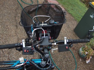
For (2) and (3), I have a couple of options. I could buy another box from Jaycar, move the buttons/switches across to the new case and solder it all up. The offending keypad is visible on the left in this photo:

3D printing probably won’t make a strong-enough part for this sort of mount, but the mount could be moulded. There’s also a question of whether I use the same buttons, or go for something more compact, perhaps a joystick button if I can get one that’s suitably waterproof.

To fix (4), we’ve purchased a replacement bracket which is nearly identical to the one I have on the left side… which is a bog-standard ~4" square angle bracket from Bunnings… about 2mm thick zinc-plated metal. Not as thick as the bracket that’s there, but should be easier to bolt the antenna mount to.

So, looks like some further refurbishment is in order.

1 Like

Hit me up if you want to make them thar buttons a whole lot sexier

Well, the buttons themselves are fine, although I did briefly have a look last night for alternate keypads… I really want a 2×2 arrangement (which I’d put on a 45° angle) and they just don’t make them that way. There’s navigational keypads too, but they were expensive as well, and I’m not sure about waterproofing.

What they do need to be though, is rugged and waterproof. It’s largely the case that has proven not so rugged, hence the idea of moulding the case. That would allow for a thicker wall thickness which would help a lot.

We did a bit more work on the bike last night, focussing on the problem area of the mounting of the VHF/UHF antenna to the top-box.

This seems to have been a success, and no amount of shaking the bike side-to-side could rattle the antenna off. The HF side of things also seems to be working well, I de-activated the ATU and put the antenna on its 40m tap, and was able to hear a couple of US stations quite clearly around 7.170MHz LSB.

We also eavesdropped on some air traffic on 128.300MHz AM. There’s quite a high noise floor at times on the 2m band and air band at the space, but that doesn’t matter: we’ve proven the station works.

The next area of attention is the keypad… this basically duplicates the up/down/“fast” and PTT buttons that would normally be seen on the standard Yaesu hand-mics. I actually have an extra button which isn’t used on the FT-857D, but is there for future use to enable directional navigation, so in total, there’s 4 direction buttons and one PTT. The PTT is in parallel with a small toggle switch, which I use for longer transmissions.

In the past for the push-buttons themselves, I’ve used these:

https://www.jaycar.com.au/ip67-rated-dome-pushbutton-switch-black/p/SP0656

They do the job, and readily available. I’m not sure if the short that developed on Sunday was internal to one of these buttons, or if it was a fault in my wiring. I strongly suspect the latter, but haven’t investigated this yet.

There’s an opportunity to go to something different. One option I’m considering is this:

There aren’t that many 2×2 keypads, but that’s one that I can get without much hassle. I suspect I’d have to etch a PCB for that, but that isn’t a show-stopper, I have some ferric chloride (of the grinning glasses brand) which I could do this with. Or there’s the mechanical method of using a rotary tool.

The other prospect was to use a 3D printed holder for a magnet and some reed switches as a crude digital joystick.

There’s no DC rail handy for powering a MCU or fancy digital logic, so we want to avoid solutions that require anything complex. The connection out of this box is a 6-way DIN; centre pin is common, the surrounding pins are for the individual buttons.

1 Like

A 3D printed joystick concept…

joystick

Look at AMS semiconductors catalog. They have hall effect joystick super magic chips.

Magnet on the bottom of the stick and the chip can be inside a sealed waterproof enclouser and give you readings.

I think this is the product you’re referring to:

https://ams.com/as5013

The downside is that the connector I’m using does not supply a power rail, so there’s nothing to power the chip. The box is completely passive, and deliberately so because it’s a generic interface: designed to work with equipment that assumes a passive external interface.

If something fails on my main rig, I have the hand-held radio as a back-up. This wiring harness is compatible with the same control panel, so my helmet (and any other headset I own, including the hard-hat people have probably seen me wear round the space) can plug into the DIN5 socket and the keypad on the handlebars plugs into the DIN6. The hand-held does expose a 3V3 rail, but with very limited current carrying capability.

I also have interfaces for my Yaesu FTM-350AR and the Garmin Rino 650, the latter of which just presents speaker and microphone connections (not even PTT). So if I need to do UHF CB, I can plug into the Garmin that’s on the bike, or if my FT-857D died completely, I could swap it out for the FTM-350AR.

Years ago, I had another interface for the Nokia 3310, which like the Garmin, does not expose a power rail. On the Garmin, I wire PTT in series with the microphone, for the Nokia I wired it in parallel so it functioned as an answer button (which with voice calling, worked a treat). A MCU or a chip like the AMS AS5013 would require a battery in such interface circuits. For this reason, anything “active” just isn’t going to work.

The reed switches are passive, readily available (Jaycar sell them), and also hermetically sealed, so are quite rugged. They’d be a drop-in replacement for the button arrangement I’m using here.

Ah - OK - didn’t realise there was no power available.

So, today I took a trip over to Jaycar to pick up a few buttons and some potting mix. The thought was I could mix that up and pour that into the bottom of the existing cases to strengthen the back wall where the screw bolts through for mounting.

Turns out, they no longer sell it. So for now, I’ve bought a new box and bought new buttons in case one of the ones I had was faulty (although the ohm meter doesn’t show a fault). I also decided that hard-wiring the indicator switches was a maintenance pain, so decided to buy some mini-XLR plugs and sockets.

The sockets went in just fine, but then I had a problem of mechanical clearance, there wasn’t enough behind the buttons to clear the socket. Everything would have to shift left. I decided to fire up Inkscape to model everything.

pad-layout

A bit of jiggling, and I came up with the above layout. The dark red are the “keep-out” zones… and the lighter red are where holes needed to be drilled/cut, with the border showing where the outline of the part is.

One sacrifice I needed to make was the original diamond-pattern of the buttons. Long term, I’d like to re-visit this and make a more compact and perhaps “sexy” looking panel, but this will do for now.

I flipped the above graphic, printed it out and stuck it to the inside of my box’s lid with thin double-sided tape. That allowed for fairly accurate positioning (my drilling though not so accurate).

That’s what it looks like now… and no the photo is not going to win awards… the Kite’s image sensor might be 8Mpixel, but it lacks a flash – it takes fine photos in broad daylight, but low-light photography is not its strong suit. On the right is the mini-XLR for connecting the indicator switch to the controller for the indicators.

Next step, I need to fix up the headphone connection on the head unit so I can hear the radio through the helmet headset again rather than the extension speaker.

So, the final patent, is the head unit on the FT-857D. This has had a skirmish with a soldering iron before (as had the body)… the 3.5mm socket wore out a few years ago but didn’t have a socket that matched the footprint. Miraculously, one of my PCB-mount switches matched the footprint for the switched-part, so I just grabbed a socket I had laying around and wired that up.

I’ve replaced the wire a couple of times, and the last time I used some stranded cable from a cheap (and I mean the nasty kind) Ethernet cable that only had two copper pairs in it. I thought this would be fine as it was still stranded cable … but no:

So, time to replace that cable. I’ll go for something a bit more flexible and see how that goes. Opening the head unit is easy enough… and the surgery needs to be on that second PCB which is pretty much all passives … it’d be tempting to re-design that board actually, but for now, it stays as-is.

This is what the pad layout looks like, and how it was soldered … yes, I fail at strain relief!

The wire I’m using is ribbon cable… stranded and quite flexible. We’ll see how it goes.

My headset is working properly now. Testing out the keypad, the cable just reaches, but that’s fine, I don’t want it much longer. So the station’s ready for the Yarraman to Wulkuraka ride, and any recreational/commuter riding I might do beforehand.

The project isn’t finished though … the keypad I definitely want to improve on to make something more compact and rugged. The last keypad actually lasted about 6 years, I built it in 2012 soon after I bought the mountain bike, so I really can’t complain, but then again, I didn’t have access to high-quality PCB manufacturing or 3D printing 6 years ago. :slight_smile:

1 Like